|
1
|
ARP coordinates and site at AD
|
521829N 0044551E
062 DEG GEO 135 M from TWR. |
|
2
|
Direction and distance from (city)
|
4.9 NM SW of Amsterdam.
|
|
3
|
Elevation / reference temperature
|
ELEV: -11 FT AMSL / T: 20.4 °C
|
|
4
|
Geoid undulation at AD ELEV PSN
|
142 FT
|
|
5
|
MAG VAR / annual change
|
2.4° E (2025) / 0.2° E
|
|
6
|
AD operator, address, telephone, telefax, email address, AFS, URL
|
AMSTERDAM AIRPORT SCHIPHOL
P.O. BOX 7501 1118 ZG SCHIPHOL THE NETHERLANDS TEL: +31 (0)20 601 9111 (ALL EXT) TEL: +31 (0)20 601 2116 (AIRPORT OFFICE/APRON MANAGEMENT SERVICE) TEL: +31 (0)20 601 2115 (AIRPORT AUTHORITY) email: [email protected] URL: https://www.schiphol.nl |
|
7
|
Types of traffic permitted (IFR/VFR)
|
IFR/VFR
|
|
8
|
Remarks
|
2. Upon request, contact the flow manager aircraft on channel 130.480 call sign "Airport One" (not monitored H24). 3. Changes in the availability of the runway and taxiway infrastructure at the airport will be promulgated by NOTAM. The NOTAM can refer to the website https://www.eham.aero where visual material relating to this subject will be shown. This material may only be used in combination with the current NOTAM. |
|
1
|
Use of aircraft stand ID signs, TWY guide lines and visual docking/parking guidance system at aircraft stands
|
Aircraft stand ID signs
- Aircraft stand identification signs: yellow characters on a black background. TWY guide lines - Guide lines on taxiway and aprons. - Aircraft stand identification markings: characters of 2 M in height. - Follow-me service AVBL on request for guidance on aprons and taxiways. - Guidance between taxiway CL and lead-in lines is interrupted over a length of APRX 15 M. - Alignment bars are only provided on aircraft stands at the A-apron and aircraft stands B16 to B36 to assist self-parking. Visual docking/parking guidance system - Guidance at aircraft stands by visual docking guidance system (see EHAM AD 2.20 paragraph 3) or marshaller is mandatory, except for self-docking aircraft stands specified in notes on chart APDC Schiphol Centre. |
|
2
|
RWY and TWY markings and LGT
|
RWY markings
- RWY 04: THR, designation, TDZ, aiming point, CL, edge. - RWY 22: THR, designation, TDZ, aiming point, CL, edge. - RWY 06: DTHR, designation, TDZ, aiming point, CL, edge. - RWY 24: THR, designation, TDZ, aiming point, CL, edge, turn pad marking. - RWY 09: DTHR, designation, TDZ, aiming point, CL, edge, RWY holding PSN. - RWY 27: THR, designation, TDZ, aiming point, CL, edge, RWY holding PSN. - RWY 18C: THR, designation, TDZ, aiming point, CL, edge. - RWY 36C: DTHR, designation, TDZ, aiming point, CL, edge. - RWY 18L: DTHR, designation, CL, edge. - RWY 36R: THR, designation, TDZ, aiming point, CL, edge. - RWY 18R: DTHR, designation, TDZ, aiming point, CL, edge. - RWY 36L: THR, designation, CL, edge, turn pad marking. RWY LGT - RWY 04: THR, edge, RWY-end. - RWY 22: THR, edge, RWY-end. - RWY 06: THR, TDZ, CL, edge, RWY-end. - RWY 24: THR, CL, edge, RWY-end. - RWY 09: THR, CL, edge, RWY-end. - RWY 27: THR, TDZ, CL, edge, RWY-end. - RWY 18C: THR, TDZ, CL, edge, RWY-end. - RWY 36C: THR, TDZ, CL, edge, RWY-end. - RWY 18L: THR, CL, edge, RWY-end. - RWY 36R: THR, TDZ, CL, edge, RWY-end. - RWY 18R: THR, TDZ, CL, edge, RWY-end. - RWY 36L: THR, CL, edge, RWY-end. TWY markings - Yellow CL, except: - TWY A19E: orange CL. - TWY A19W: blue CL. - TWY N2 - TWY E6: CL continues over the full width of RWY 09/27 to provide additional taxiing guidance. - TWY S7W - TWY S8: CL continues over the full width of RWY 06/24 to provide additional taxiing guidance. - CL interrupted prior to connecting to TWY: - TWY N2: when vacating RWY 27. - TWY E10: when vacating RWY 36R. - TWY E1 into TWY A8: after vacating RWY 36R. - White marked guidance lines parallel to the yellow CL marking (provided east of RWY 18L/36R) and white coloured ACFT stand designators are intended for ACFT towing operations and should be disregarded by pilots. - TWY-RWY intersections: mandatory instruction markings and signs, enhanced TWY CL. - MAX SPAN information markings. - No-entry locations: single marking reading NO ENTRY centered around CL. - Intermediate HLDG PSN. TWY LGT - Green CL, except: - TWY A19E: alternating green/orange CL. - TWY A19W: alternating green/blue CL. - RWY exits and TWYs crossing RWY: alternating green/yellow CL (between RWY CL and perimeter(s) of ILS sensitive area). - take-off intersections not for use during LVP: no CL. - taxiways on Schiphol East: no CL. - TWY edge: generally blue LGT in curves; blue retroreflective edge markers on straight sections. - Intermediate HLDG PSN. - Runway guard lights: provided at hot spots, standard towing routes and other designated locations. |
|
3
|
Stop bars
|
- if associated with an active runway during reduced and low visibility circumstances (TDZ RVR <= 1500 M and/or ceiling <= 300 FT); - H24 at dedicated runway crossings to avoid runway incursion in all visibility conditions; - H24 at the "NO ENTRY" TWY E1, G3, W6 and N9; - on TWY Y (Y1 and Y2) and TWY Z (Z1 and Z2), depending on the use of RWY 18C/36C; - on RWY 09, west of the intersection with RWY 18L/36R, depending on the use of RWY 18L/36R. |
|
4
|
Remarks
|
Visual docking/parking guidance system
- For parking guidance on K-apron contact the handler. RWY markings - RWY designation marking: character height of 18 M. - RWY 09/27: RWY holding position marking is applied over the full width of RWY 09/27, west of RWY 18L, to safeguard RWY 18L from taxiing aircraft crossing RWY 09/27 via TWY N2. RWY LGT - No RWY turn pad LGT provided at the end of RWY 24 and RWY 36L (see EHAM AD 2.23). TWY markings - - MAX span information markings are placed to indicate TWYs where operations are limited to aircraft not exceeding the maximum wingspan specified. TWY LGT - CL lights are placed based on the principle of cockpit over centre line for all aircraft types, except A340-600, A350-1000, A380, B777-300 and larger. For those aircraft oversteering is required. - For the configuration of CL lights on RWY entries including when used during low visibility, see EHAM AD 2.23 paragraph |
|
Area 2
|
|||||
|---|---|---|---|---|---|
|
OBST ID / designation
|
OBST type
|
OBST position
|
ELEV/HGT (FT)
|
Markings /
type, colour LGT |
Remarks
|
|
1
|
2
|
3
|
4
|
5
|
6
|
|
EHAM001
|
Crane
|
522127.9N 0044822.4E
|
240 / 243
|
Flag /
Night R |
True bearing from ARP 027 DEG, DIST 6180 M.
|
|
EHAM002
|
Crane
|
522126.5N 0044823.3E
|
197 / 201
|
Flag /
Night R |
True bearing from ARP 028 DEG, DIST 6150 M.
|
|
EHAM008
|
Crane
|
521705.9N 0044553.5E
|
119 / 132
|
Flag /
Night R |
2075 M beyond TORA RWY 22 and 141 M left of EXTD RCL.
|
|
EHAM009
|
Crane
|
521709.3N 0044552.5E -
521705.4N 0044559.7E. |
125 / 138
|
Flag /
Night R |
2055 M beyond TORA RWY 22 and 88 M left of EXTD RCL.
MON-FRI 0600-1700 (0500-1600) |
|
EHAM010
|
Crane
|
521808.8N 0044146.6E -
521809.7N 0044152.9E. |
197 / 211
|
Flag /
Night R |
True bearing from ARP 263 DEG, DIST 4555 M.
|
|
EHAM011
|
Crane
|
521808.8N 0044146.6E -
521809.7N 0044152.9E. |
250 / 264
|
Flag /
Night R |
True bearing from ARP 263 DEG, DIST 4555 M.
|
|
EHAM012
|
Crane
|
522127.6N 0043914.6E
|
243 / 245
|
Flag /
Night R |
True bearing from ARP 307 DEG, DIST 9210 M.
|
|
EHAM013
|
Crane
|
522127.6N 0043914.6E
|
188 / 200
|
Flag /
Night R |
True bearing from ARP 307 DEG, DIST 9210 M.
|
|
EHAM014
|
Crane
|
522126.9N 0043912.5E
|
335 / 348
|
Flag /
Night R |
True bearing from ARP 306 DEG, DIST 9335 M.
|
|
EHAM015
|
Crane
|
522045.7N 0045023.8E -
522014.9N 0045017.9E - 522013.5N 0045138.5E. |
197 / 199
|
Flag /
Night R |
3500 M beyond TORA RWY 04 on extended RCL.
|
|
EHAM016
|
Crane
|
522045.7N 0045023.8E -
522014.9N 0045017.9E - 522013.5N 0045138.5E. |
151 / 153
|
Flag /
Night R |
3500 M beyond TORA RWY 04 on extended RCL.
|
|
EHAM017
|
Crane
|
522033.7N 0044942.0E -
522031.2N 0044947.4E. |
275 / 278
|
Flag /
Night R |
True bearing from ARP 050 DEG, DIST 5760 M.
|
|
EHAM018
|
Crane
|
521744.8N 0044205.1E
|
273 / 289
|
Flag /
Night R |
True bearing from ARP 252 DEG, DIST 4360 M.
2 cranes |
|
EHAM019
|
Crane
|
521747.9N 0044218.1E
|
197 / 210
|
Flag /
Night R |
True bearing from ARP 252 DEG, DIST 4200 M.
|
|
EHAM020
|
Crane
|
521747.9N 0044218.1E
|
233 / 246
|
Flag /
Night R |
True bearing from ARP 252 DEG, DIST 4200 M.
|
All obstacles in take-off area are marked and lighted day and night. See all charts AOC type A.
No obstacle data sets available for area 2 and 3.
No obstacle data sets available for area 2 and 3.
|
1
|
Associated MET office
|
DE BILT
|
|
2
|
Hours of service
MET office outside hours |
Hours of service
H24 MET office outside hours NIL |
|
3
|
Office responsible for TAF preparation
Period of validity |
De Bilt
30 HR |
|
4
|
Trend forecast
Interval of issuance |
TREND
Every 30 minutes for international METAR, maximum 30 minutes for local display and broadcast on ATIS. |
|
5
|
Briefing/consultation provided
|
Briefing on request from MWO-De Bilt by telephone after self-briefing.
TEL: +31 (0)30 220 6721 Staff TEL: 0900 202 3341 Briefing low level flights (IFR/VFR). TEL: 0900 202 3343 Briefing IFR flights above FL 100. TEL: 0900 202 3340 Briefing balloon flights within Amsterdam FIR. |
|
6
|
Flight documentation
Language(s) used |
Reports, forecasts, charts.
English, Dutch. |
|
7
|
Charts and other information available for briefing or consultation
|
S, P, W, T
|
|
8
|
Supplementary equipment available for providing information
|
WXR, APT
|
|
9
|
ATS units provided with information
|
Amsterdam ACC and FIC, Schiphol TWR, Schiphol APP.
Also service to JRCC Den Helder. |
|
10
|
Additional information (limitation of service, etc.)
|
Briefing/consultation provided
- charge for TEL briefings and consultations is € 0,50/MIN. Note: due to environmental influences the wind report for RWY 36R is not representative for the wind conditions at TDZ; wind speed from sector 080-120 DEG is underestimated up to 15 percent. |
|
RWY designation
|
True BRG
|
Dimensions of RWY (M)
|
Strength (PCN) and surface of RWY and SWY
|
THR coordinates
RWY end coordinates THR GUND |
THR ELEV and highest ELEV of TDZ of precision APCH RWY
|
|---|---|---|---|---|---|
|
1
|
2
|
3
|
4
|
5
|
6
|
|
04
|
041.25°
|
2020 x 45
|
RWY: 79/F/C/W/T
Asphalt SWY: NIL |
THR:
521801.35N 0044700.55E RWY end: 521850.51N 0044810.90E THR GUND: 142 FT |
THR: -13 FT
TDZ: NIL |
|
22
|
221.27°
|
2020 x 45
|
RWY: 79/F/C/W/T
Asphalt SWY: NIL |
THR:
521850.51N 0044810.89E RWY end: 521801.38N 0044700.60E THR GUND: 142.0 FT |
THR: -13.7 FT
TDZ: -12.1 FT |
|
06
|
057.92°
|
3439 x 45
|
RWY: 89/F/C/W/T
Asphalt SWY: NIL |
THR:
521720.78N 0044414.01E RWY end: 521815.66N 0044636.93E THR GUND: 142.0 FT |
THR: -11.0 FT
TDZ: -11.6 FT |
|
24
|
237.95°
|
3439 x 45
|
RWY: 89/F/C/W/T
Asphalt SWY: NIL |
THR:
521815.66N 0044636.93E RWY end: 521716.57N 0044403.07E THR GUND: 142 FT |
THR: -12 FT
TDZ: NIL |
|
09
|
086.78°
|
3453 x 45
|
RWY: 89/F/C/W/T
Asphalt SWY: NIL |
THR:
521900.09N 0044451.57E RWY end: 521906.16N 0044748.83E THR GUND: 142 FT |
THR: -12 FT
TDZ: NIL |
|
27
|
266.82°
|
3453 x 45
|
RWY: 89/F/C/W/T
Asphalt SWY: NIL |
THR:
521906.16N 0044748.88E RWY end: 521859.92N 0044446.83E THR GUND: 142.0 FT |
THR: -12.0 FT
TDZ: -12.2 FT |
|
18C
|
183.22°
|
3300 x 45
|
RWY: 89/F/C/W/T
Asphalt SWY: NIL |
THR:
521953.04N 0044424.11E RWY end: 521806.42N 0044414.32E THR GUND: 142.0 FT |
THR: -12.1 FT
TDZ: -12.0 FT |
|
36C
|
003.22°
|
3300 x 45
|
RWY: 89/F/C/W/T
Asphalt SWY: NIL |
THR:
521820.99N 0044415.69E RWY end: 521953.04N 0044424.11E THR GUND: 142.0 FT |
THR: -12.0 FT
TDZ: -12.0 FT |
|
18L
|
183.25°
|
3400 x 45
|
RWY: 89/F/C/W/T
Asphalt SWY: NIL |
THR:
521858.19N 0044646.89E RWY end: 521726.96N 0044638.45E THR GUND: 142 FT |
THR: -12 FT
TDZ: NIL |
|
36R
|
003.25°
|
3400 x 45
|
RWY: 89/F/C/W/T
Asphalt SWY: NIL |
THR:
521726.97N 0044638.45E RWY end: 521858.19N 0044646.89E THR GUND: 142.0 FT |
THR: -11.3 FT
TDZ: -11.1 FT |
|
18R
|
183.20°
|
3800 x 60
|
RWY: 89/F/C/W/T
Asphalt SWY: NIL |
THR:
522136.93N 0044242.21E RWY end: 521942.89N 0044231.81E THR GUND: 142.0 FT |
THR: -13.2 FT
TDZ: -13.2 FT |
|
36L
|
003.20°
|
3800 x 60
|
RWY: 89/F/C/W/T
Asphalt SWY: NIL |
THR:
521942.88N 0044231.81E RWY end: 522145.65N 0044243.01E THR GUND: 142 FT |
THR: -12 FT
TDZ: NIL |
|
RWY designation
|
Slope of RWY-SWY
|
SWY dimensions (M)
|
CWY dimensions (M)
|
Strip dimensions (M)
|
RESA dimensions (M)
|
Location and description of arresting system
|
OFZ
|
|---|---|---|---|---|---|---|---|
|
1
|
7
|
8
|
9
|
10
|
11
|
12
|
13
|
|
04
|
< -0.01%
|
NIL
|
60 x 150
|
2140 x 280
|
220 x 90
|
NIL
|
NIL
|
|
22
|
< 0.01%
|
NIL
|
60 x 150
|
2140 x 280
|
180 x 90
|
NIL
|
NIL
|
|
06
|
< -0.01%
|
NIL
|
60 x 150
|
3559 x 280
|
240 x 90
|
NIL
|
AVBL
|
|
24
|
< 0.01%
|
NIL
|
60 x 150
|
3559 x 280
|
90 x 90
|
NIL
|
NIL
|
|
09
|
< -0.01%
|
NIL
|
60 x 150
|
3573 x 280
|
150 x 90
|
NIL
|
NIL
|
|
27
|
< 0.01%
|
NIL
|
60 x 150
|
3573 x 280
|
95 x 90
|
NIL
|
AVBL
|
|
18C
|
< 0.01%
|
NIL
|
60 x 150
|
3420 x 280
|
120 x 90
|
NIL
|
AVBL
|
|
36C
|
< -0.01%
|
NIL
|
60 x 150
|
3420 x 280
|
230 x 90
|
NIL
|
AVBL
|
|
18L
|
< 0.01%
|
NIL
|
60 x 150
|
3520 x 280
|
240 x 90
|
NIL
|
NIL
|
|
36R
|
< -0.01%
|
NIL
|
NIL
|
3520 x 280
|
240 x 90
|
NIL
|
AVBL
|
|
18R
|
0.01%
|
NIL
|
NIL
|
3920 x 280
|
240 x 120
|
NIL
|
AVBL
|
|
36L
|
-0.01%
|
NIL
|
60 x 150
|
3920 x 280
|
240 x 120
|
NIL
|
NIL
|
|
RWY designation
|
Remarks
|
|---|---|
|
1
|
14
|
|
04
|
Strength of RWY
- an unlimited use will be permitted for aircraft with an AUW <= 5700 KG. - strength restricted for RWY shoulders of 7.5 M width on both sides. - prohibited (landing and take-off) for aircraft with a MTOM exceeding 600 000 KG due to insufficient load bearing capacity of related runway and taxiway bridges. - prohibited for ICAO/EASA code letter F aircraft. |
|
22
|
Strength of RWY
- an unlimited use will be permitted for aircraft with an AUW <= 5700 KG. - strength restricted for RWY shoulders of 7.5 M width on both sides. - prohibited (landing and take-off) for aircraft with a MTOM exceeding 600 000 KG due to insufficient load bearing capacity of related runway and taxiway bridges. - prohibited for ICAO/EASA code letter F aircraft. |
|
06
|
Strength of RWY
- an unlimited use will be permitted for aircraft with an AUW <= 5700 KG. - strength restricted for RWY shoulders of 15 M width on both sides. - prohibited (landing and take-off) for aircraft with a MTOM exceeding 600 000 KG due to insufficient load bearing capacity of related runway and taxiway bridges. Dimensions of RWY - a turn-around area is AVBL at the beginning of the RWY. |
|
24
|
Strength of RWY
- an unlimited use will be permitted for aircraft with an AUW <= 5700 KG. - strength restricted for RWY shoulders of 15 M width on both sides. - prohibited (landing and take-off) for aircraft with a MTOM exceeding 600 000 KG due to insufficient load bearing capacity of related runway and taxiway bridges. Dimensions of RWY - a turn-around area is AVBL at the end of the RWY. |
|
09
|
Strength of RWY
- an unlimited use will be permitted for aircraft with an AUW <= 5700 KG. - strength restricted for RWY shoulders of 15 M width on both sides. - prohibited (landing and take-off) for aircraft with a MTOM exceeding 600 000 KG due to insufficient load bearing capacity of related runway and taxiway bridges. |
|
27
|
Strength of RWY
- an unlimited use will be permitted for aircraft with an AUW <= 5700 KG. - strength restricted for RWY shoulders of 15 M width on both sides. - prohibited (landing and take-off) for aircraft with a MTOM exceeding 600 000 KG due to insufficient load bearing capacity of related runway and taxiway bridges. |
|
18C
|
Strength of RWY
- an unlimited use will be permitted for aircraft with an AUW <= 5700 KG. - strength restricted for RWY shoulders of 15 M width on both sides. |
|
36C
|
Strength of RWY
- an unlimited use will be permitted for aircraft with an AUW <= 5700 KG. - strength restricted for RWY shoulders of 15 M width on both sides. |
|
18L
|
Strength of RWY
- an unlimited use will be permitted for aircraft with an AUW <= 5700 KG. - strength restricted for RWY shoulders of 15 M width on both sides. - prohibited (landing and take-off) for aircraft with a MTOM exceeding 600 000 KG due to insufficient load bearing capacity of related runway and taxiway bridges. |
|
36R
|
Strength of RWY
- an unlimited use will be permitted for aircraft with an AUW <= 5700 KG. - strength restricted for RWY shoulders of 15 M width on both sides. - prohibited (landing and take-off) for aircraft with a MTOM exceeding 600 000 KG due to insufficient load bearing capacity of related runway and taxiway bridges. |
|
18R
|
Strength of RWY
- an unlimited use will be permitted for aircraft with an AUW <= 5700 KG. - strength restricted for RWY shoulders of 7.5 M width on both sides. |
|
36L
|
Strength of RWY
- an unlimited use will be permitted for aircraft with an AUW <= 5700 KG. - strength restricted for RWY shoulders of 7.5 M width on both sides. Dimensions of RWY - a turn-around area is AVBL at the end of the RWY. |
|
RWY designator
|
TORA
(M) |
TODA
(M) |
ASDA
(M) |
LDA
(M) |
Remarks
|
|---|---|---|---|---|---|
|
1
|
2
|
3
|
4
|
5
|
6
|
|
04
|
NIL
|
NIL
|
NIL
|
2020
|
NIL
|
|
04
|
1909
|
1969
|
1909
|
NIL
|
Take-off from intersection with TWY: G5
|
|
22
|
NIL
|
NIL
|
NIL
|
2020
|
NIL
|
|
22
|
2015
|
2075
|
2015
|
NIL
|
Take-off from intersection with TWY: G1
|
|
22
|
1714
|
1774
|
1714
|
NIL
|
Take-off from intersection with TWY: G2
|
|
06
|
3439
|
3499
|
3439
|
3195
|
DTHR 244 M.
|
|
06
|
2596
|
2656
|
2596
|
NIL
|
Take-off from intersection with TWY: S1
|
|
06
|
2596
|
2656
|
2596
|
NIL
|
Take-off from intersection with TWY: S10
|
|
24
|
NIL
|
NIL
|
NIL
|
3439
|
NIL
|
|
24
|
3435
|
3495
|
3435
|
NIL
|
Take-off from intersection with TWY: S7E
|
|
24
|
3266
|
3326
|
3266
|
NIL
|
Take-off from intersection with TWY: S8
|
|
24
|
3245
|
3305
|
3245
|
NIL
|
Take-off from intersection with TWY: S6
|
|
24
|
3205
|
3265
|
3205
|
NIL
|
Take-off from intersection with TWY: S5
|
|
24
|
2611
|
2671
|
2611
|
NIL
|
Take-off from intersection with TWY: S4
|
|
24
|
1981
|
2041
|
1981
|
NIL
|
Take-off from intersection with TWY: S3
|
|
09
|
NIL
|
NIL
|
NIL
|
3363
|
DTHR 90 M.
|
|
09
|
3434
|
3494
|
3434
|
NIL
|
Take-off from intersection with TWY: N5
|
|
09
|
2400
|
2460
|
2400
|
NIL
|
Take-off from intersection with TWY: N4
|
|
09
|
1881
|
1941
|
1881
|
NIL
|
Take-off from intersection with TWY: N3
|
|
27
|
3453
|
3513
|
3453
|
3453
|
NIL
|
|
18C
|
NIL
|
NIL
|
NIL
|
3300
|
NIL
|
|
18C
|
3271
|
3331
|
3271
|
NIL
|
Take-off from intersection with TWY: W1
|
|
18C
|
3072
|
3132
|
3072
|
NIL
|
Take-off from intersection with TWY: W2
|
|
18C
|
2681
|
2741
|
2681
|
NIL
|
Take-off from intersection with TWY: W3
|
|
18C
|
2378
|
2438
|
2378
|
NIL
|
Take-off from intersection with TWY: W4
|
|
18C
|
2090
|
2150
|
2090
|
NIL
|
Take-off from intersection with TWY: W5
|
|
36C
|
NIL
|
NIL
|
NIL
|
2850
|
DTHR 450 M.
|
|
36C
|
3300
|
3360
|
3300
|
NIL
|
Take-off from intersection with TWY: W10
|
|
36C
|
3297
|
3357
|
3297
|
NIL
|
Take-off from intersection with TWY: W11
|
|
36C
|
3050
|
3110
|
3050
|
NIL
|
Take-off from intersection with TWY: W9
|
|
36C
|
3050
|
3110
|
3050
|
NIL
|
Take-off from intersection with TWY: W12
|
|
36C
|
2695
|
2755
|
2695
|
NIL
|
Take-off from intersection with TWY: W8
|
|
36C
|
2131
|
2191
|
2131
|
NIL
|
Take-off from intersection with TWY: W7
|
|
18L
|
3400
|
3460
|
3400
|
2825
|
Not AVBL for landing, except in case of an emergency.
DTHR 575 M. |
|
18L
|
2820
|
2880
|
2820
|
NIL
|
Take-off from intersection with TWY: E5
|
|
18L
|
2582
|
2642
|
2582
|
NIL
|
Take-off from intersection with TWY: E4
|
|
18L
|
2547
|
2607
|
2547
|
NIL
|
Take-off from intersection with TWY: E8
|
|
18L
|
2114
|
2174
|
2114
|
NIL
|
Take-off from intersection with TWY: E2
|
|
36R
|
NIL
|
NIL
|
NIL
|
2825
|
The section of 575 m beyond the displaced RWY-end shall not be used.
|
|
18R
|
NIL
|
NIL
|
NIL
|
3530
|
DTHR 270 M.
|
|
36L
|
3800
|
3860
|
3800
|
3800
|
Not AVBL for landing, except in case of an emergency.
|
|
36L
|
3247
|
3307
|
3247
|
NIL
|
Take-off from intersection with TWY: V3
|
|
36L
|
2748
|
2808
|
2748
|
NIL
|
Take-off from intersection with TWY: V2
|
|
36L
|
2148
|
2208
|
2148
|
NIL
|
Take-off from intersection with TWY: V1
|
|
RWY
designator |
APCH LGT
type length INTST |
THR LGT
colour WBAR |
VASIS
location/slope MEHT |
TDZ LGT
length |
RWY CL LGT
length spacing colour INTST |
|---|---|---|---|---|---|
|
1
|
2
|
3
|
4
|
5
|
6
|
|
04
|
SALS
450 M LIH |
G
NIL |
PAPI
Left side/3.0° 50 FT |
NIL
|
NIL
|
|
22
|
SALS
450 M LIH |
G
NIL |
PAPI
Left side/3.1° 48 FT |
NIL
|
NIL
|
|
06
|
CAT II/III
900 M LIH |
G
NIL |
PAPI
Left side/3.0° 70 FT |
900 M
|
3439 M
15 M W LIH |
|
24
|
NIL
|
G
NIL |
PAPI
Both sides/3.0° 70 FT |
NIL
|
3439 M
15 M W LIH |
|
09
|
NIL
|
G
NIL |
PAPI
Left side/3.0° 64 FT |
NIL
|
3453 M
15 M W LIH |
|
27
|
CAT II/III
750 M LIH |
G
NIL |
PAPI
Left side/3.0° 67 FT |
900 M
|
3453 M
30 M W LIH |
|
18C
|
CAT II/III
900 M LIH |
G
NIL |
PAPI
Left side/3.0° 68 FT |
900 M
|
3300 M
15 M W LIH |
|
36C
|
CAT II/III
900 M LIH |
G
NIL |
PAPI
Left side/3.0° 70 FT |
900 M
|
3300 M
15 M W LIH |
|
18L
|
NIL
|
G
NIL |
NIL
|
NIL
|
3400 M
15 M W LIH |
|
36R
|
CAT II/III
900 M LIH |
G
NIL |
PAPI
Left side/3.0° 70 FT |
900 M
|
2825 M
15 M W LIH |
|
18R
|
CAT II/III
900 M LIH |
G
NIL |
PAPI
Left side/3.0° 70 FT |
900 M
|
3800 M
15 M W LIH |
|
36L
|
NIL
|
G
NIL |
NIL
|
NIL
|
3800 M
15 M W LIH |
|
RWY
designator |
RWY edge LGT
length spacing colour INTST |
RWY end LGT
colour WBAR |
SWY LGT
length colour |
Remarks
|
|---|---|---|---|---|
|
1
|
7
|
8
|
9
|
10
|
|
04
|
2200 M
50 M W LIH |
R
NIL |
NIL
|
PAPI
- For aircraft with eye-to-wheel height (EWH) of more than 8 M (26.2 FT) minimum wheel height over threshold (WTH) of 6 M is not guaranteed. RWY edge LGT - Spacing: irregular interval between edge LGT at intersection with TWY G3. - Colour: white/yellow. LED LGT - LED lights used for PAPI, THR and end lights. |
|
22
|
2020 M
50 M W LIH |
R
NIL |
NIL
|
PAPI
- For aircraft with eye-to-wheel height (EWH) of more than 8 M (26.2 FT) minimum wheel height over threshold (WTH) of 6 M is not guaranteed. PAPI not to be used by B747 because of limited MEHT. RWY edge LGT - Spacing: irregular interval between edge LGT at intersection with TWY G3. - Colour: white/yellow. LED LGT - LED lights used for THR and end lights. |
|
06
|
3439 M
60 M W LIH |
R
NIL |
NIL
|
RWY centre line LGT
- Colour: white from THR to 900 M before RWY-end; white/red from 900 M before RWY-end to 300 M before RWY-end; red from 300 M before RWY-end to RWY-end. RWY edge LGT - Colour: red from beginning of RWY to DTHR; white from DTHR to 600 M before RWY-end; yellow from 600 M before RWY-end to RWY-end. LED LGT - LED lights used for APCH, PAPI, THR, TDZ, CL, edge and end lights. |
|
24
|
3439 M
60 M W LIH |
R
NIL |
NIL
|
RWY centre line LGT
- Colour: white from THR to 900 M before RWY-end; white/red from 900 M before RWY-end to 300 M before RWY-end; red from 300 M before RWY-end to RWY-end. RWY edge LGT - Colour: white from THR to 600 M before RWY-end; yellow from 600 M before RWY-end to RWY-end. LED LGT - LED lights used for PAPI, THR, CL, edge and end lights. |
|
09
|
3453 M
30 M W LIH |
R
NIL |
NIL
|
RWY centre line LGT
- Colour: white from THR to 900 M before RWY-end; white/red from 900 M before RWY-end to 300 M before RWY-end; red from 300 M before RWY-end to RWY-end. RWY edge LGT - Colour: red from beginning of RWY to DTHR; white from DTHR to 600 M before RWY-end; yellow from 600 M before RWY-end to RWY-end. LED LGT - LED lights used for PAPI, THR, CL, edge and end lights. |
|
27
|
3453 M
30 M W LIH |
R
NIL |
NIL
|
RWY centre line LGT
- Colour: white from THR to 900 M before RWY-end; white/red from 900 M before RWY-end to 300 M before RWY-end; red from 300 M before RWY-end to RWY-end. RWY edge LGT - Colour: white from THR to 600 M before RWY-end; yellow from 600 M before RWY-end to RWY-end. LED LGT - LED lights used for APCH, PAPI, THR, TDZ, CL, edge and end lights. |
|
18C
|
3300 M
30 M W LIH |
R
NIL |
NIL
|
RWY centre line LGT
- Colour: white from THR to 900 M before RWY-end; white/red from 900 M before RWY-end to 300 M before RWY-end; red from 300 M before RWY-end to RWY-end. RWY edge LGT - Colour: white from THR to 600 M before RWY-end; yellow from 600 M before RWY-end to RWY-end. LED LGT - LED lights used for APCH, PAPI, THR, TDZ, CL, edge and end lights. |
|
36C
|
3300 M
30 M W LIH |
R
NIL |
NIL
|
RWY centre line LGT
- Colour: white from THR to 900 M before RWY-end; white/red from 900 M before RWY-end to 300 M before RWY-end; red from 300 M before RWY-end to RWY-end. RWY edge LGT - Colour: red from beginning of RWY to DTHR; white from DTHR to 600 M before RWY-end; yellow from 600 M before RWY-end to RWY-end. LED LGT - LED lights used for APCH, PAPI, THR, TDZ, CL, edge and end lights. |
|
18L
|
3400 M
30 M W LIH |
R
NIL |
NIL
|
RWY centre line LGT
- Colour: white from THR to 900 M before RWY-end; white/red from 900 M before RWY-end to 300 M before RWY-end; red from 300 M before RWY-end to RWY-end. RWY edge LGT - Colour: red from beginning of RWY to DTHR; white from DTHR to 600 M before RWY-end; yellow from 600 M before RWY-end to RWY-end. LED LGT - LED lights used for THR, CL, edge and end lights. |
|
36R
|
2825 M
30 M W LIH |
R
NIL |
NIL
|
RWY centre line LGT
- Colour: white from THR to 900 M before RWY-end; white/red from 900 M before RWY-end to 300 M before RWY-end; red from 300 M before RWY-end to RWY-end. - No lights beyond displaced RWY-end. RWY edge LGT - Colour: white from THR to 600 M before RWY-end; yellow from 600 M before RWY-end to RWY-end. - No lights beyond displaced RWY-end. LED LGT - LED lights used for APCH, PAPI, THR, TDZ, CL, edge and end lights. |
|
18R
|
3800 M
60 M W LIH |
R
NIL |
NIL
|
RWY centre line LGT
- Colour: white from THR to 900 M before RWY-end; white/red from 900 M before RWY-end to 300 M before RWY-end; red from 300 M before RWY-end to RWY-end. RWY edge LGT - Colour: red from beginning of RWY to DTHR; white from DTHR to 600 M before RWY-end; yellow from 600 M before RWY-end to RWY-end. LED LGT - LED lights used for APCH, PAPI, THR, TDZ, CL, edge and end lights. |
|
36L
|
3800 M
60 M W LIH |
R
NIL |
NIL
|
RWY centre line LGT
- Colour: white from THR to 900 M before RWY-end; white/red from 900 M before RWY-end to 300 M before RWY-end; red from 300 M before RWY-end to RWY-end. RWY edge LGT - Colour: white from THR to 600 M before RWY-end; yellow from 600 M before RWY-end to RWY-end. LED LGT - LED lights used for THR, CL, edge and end lights. |
|
1
|
ABN/IBN location, characteristics and hours of operation
|
NIL
|
|
2
|
LDI location and LGT
Anemometer location and LGT |
LDI: NIL
Anemometer: 105 M FM centre line near TDZ RWY 06, 18C, 18R, 27, 36C, 36L and 36R; 105 M FM centre line and 100 M FM TDZ RWY 22. |
|
3
|
TWY edge and centre line lighting
|
See EHAM AD 2.9.
|
|
4
|
Secondary power supply
Switchover time |
RWYs: generator and battery; TWYs: generator.
RWYs: within 1 second; TWYs: within 15 seconds. |
|
5
|
Remarks
|
NIL
|
|
1
|
Coordinates TLOF or THR of FATO
Geoid undulation |
Schiphol-East:
Intersection RWY 04/22 and TWY G2/G8: 521842.77N 0044759.82E, 142 FT TWY G between TWY G1 and hangar 1: 521849N 0044822E, 142 FT |
|
2
|
TLOF and/or FATO elevation
|
Intersection RWY 04/22 and TWY G2/G8: -12.1 FT
TWY G between TWY G1 and hangar 1: -13.2 FT |
|
3
|
TLOF and FATO area dimensions, surface, strength, marking
|
Intersection RWY 04/22 and TWY G2/G8: rectangular 35 x 30 M
TWY G between TWY G1 and hangar 1: square 14 x 14 M |
|
4
|
True BRG of FATO
|
Intersection RWY 04/22 and TWY G2/G8: 041.25/221.27°
TWY G between TWY G1 and hangar 1: NIL |
|
5
|
Declared distances available
|
NIL
|
|
6
|
APCH and FATO lighting
|
NIL
|
|
7
|
Remarks
|
Intersection RWY 04/22 and TWY G2/G8: TLOF: green omnidirectional lights, interval 5 M; no markings.
TWY G between TWY G1 and hangar 1: only for State police helicopters; at ATC discretion. TLOF not lighted. |
|
Designation and lateral limits
|
Vertical limits
|
Airspace classification
|
ATS unit
call sign language(s) |
Transition altitude
|
Hours of applicability
|
Remarks
|
|---|---|---|---|---|---|---|
|
1
|
2
|
3
|
4
|
5
|
6
|
7
|
|
SCHIPHOL CTR
(EHAM) 522454N 0043805E - 522821N 0043824E - 522801N 0044812E - 522621N 0044803E along clockwise arc (radius 8 NM, centre 521829N 0044551E) - 522454N 0043805E. |
C
|
Schiphol Tower
English |
3000 FT AMSL
|
H24
|
Restricted to ACFT capable of maintaining two-way radio communication with Schiphol TWR, unless prior permission from Aerodrome Control has been obtained. Such permission will only be given in extraordinary cases.
|
|
Service
designation |
Call sign
|
Channel(s)
|
SATVOICE NR
|
Logon address
|
Hours of operation
|
Remarks
|
|---|---|---|---|---|---|---|
|
1
|
2
|
3
|
4
|
5
|
6
|
7
|
|
APP
|
Schiphol Approach/Departure
|
119.055
|
NIL
|
NIL
|
H24
|
PRI
At ATC discretion. Intermediate approach. |
|
118.080
|
NIL
|
NIL
|
H24
|
At ATC discretion.
· Intermediate approach. At ATC discretion. Intermediate approach. |
||
|
312.375
|
NIL
|
NIL
|
H24
|
At ATC discretion. Intermediate approach.
|
||
|
121.205
|
NIL
|
NIL
|
H24
|
PRI
At ATC discretion. Intermediate approach. Departures. |
||
|
Schiphol Arrival
|
118.405
|
NIL
|
NIL
|
H24
|
At ATC discretion.
· Intermediate and final approach main RWY. At ATC discretion. Intermediate and final approach main RWY. |
|
|
126.680
|
NIL
|
NIL
|
H24
|
At ATC discretion. Intermediate and final approach main RWY.
|
||
|
Schiphol Approach
|
131.155
|
NIL
|
NIL
|
H24
|
At ATC discretion.
At ATC discretion. |
|
|
TWR
|
Schiphol Tower
|
119.230
|
NIL
|
NIL
|
H24
|
PRI
RWY 04/22 and 18L/36R. VDF. |
|
118.105
|
NIL
|
NIL
|
H24
|
PRI
RWY 18C/36C. VDF. |
||
|
118.280
|
NIL
|
NIL
|
H24
|
PRI
RWY 18R/36L. VDF. |
||
|
135.110
|
NIL
|
NIL
|
H24
|
PRI
RWY 06/24. VDF. |
||
|
362.875
|
NIL
|
NIL
|
H24
|
At ATC discretion.
|
||
|
Schiphol Delivery
|
121.980
|
NIL
|
NIL
|
H24
|
Clearance delivery (start-up control VFR only).
|
|
|
121.590
|
NIL
|
NIL
|
H24
|
At ATC discretion.
|
||
|
Schiphol Planner
|
121.655
|
NIL
|
NIL
|
H24
|
Outbound planner.
|
|
|
121.590
|
NIL
|
NIL
|
H24
|
At ATC discretion.
|
||
|
ATC Operational Information Schiphol
|
131.355
|
NIL
|
NIL
|
H24
|
Broadcast of information about expected RWY combinations related to SIDs, during peak HR.
|
|
|
GND
|
Schiphol Ground
|
121.560
|
NIL
|
NIL
|
H24
|
Ground control (see EHAM AD 2.20, EHAM AD 2.22 and AD 2.EHAM-GMC).
|
|
121.705
|
NIL
|
NIL
|
H24
|
Ground control (see EHAM AD 2.20, EHAM AD 2.22 and AD 2.EHAM-GMC).
|
||
|
121.805
|
NIL
|
NIL
|
H24
|
Ground control (see EHAM AD 2.20, EHAM AD 2.22 and AD 2.EHAM-GMC).
|
||
|
121.905
|
NIL
|
NIL
|
H24
|
Ground control (see EHAM AD 2.20, EHAM AD 2.22 and AD 2.EHAM-GMC).
|
||
|
121.590
|
NIL
|
NIL
|
H24
|
At ATC discretion.
|
||
|
ATIS
|
Schiphol Arrival Information
|
132.980
|
NIL
|
NIL
|
H24
|
ATIS service also AVBL by ACARS for ACFT equipped with ACARS-MU (AEEC 622 and 623 compliant).
|
|
Schiphol Departure Information
|
122.205
|
NIL
|
NIL
|
H24
|
ATIS service also AVBL by ACARS for ACFT equipped with ACARS-MU (AEEC 622 and 623 compliant).
|
|
Type of aid
MAG VAR Supported OPS ILS CAT GBAS facility (VOR/ILS/MLS declination) |
ID
|
Frequency
CH Service provider Reference path ID |
Hours of operation
|
Position of transmitting antenna
|
DME: ELEV
transmitting antenna GBAS: ELEV ellipsoid height reference point SBAS: ellipsoid height LTP/FTP |
GBAS
reference point service volume radius |
Remarks
|
|---|---|---|---|---|---|---|---|
|
1
|
2
|
3
|
4
|
5
|
6
|
7
|
8
|
|
DVOR/DME
(02° E) (decl.: 2°E) |
SPL
|
108.400 MHz
CH 21X |
H24 |
521955.7N
0044459.6E |
0 FT
|
NIL
|
60 NM/250 FL
in sector 000°-360° MAG |
|
DME 06
|
KAG
|
CH 42Y
|
H24 |
521721.9N
0044432.9E |
0 FT
|
NIL
|
DME reads zero at THR RWY 06.
Distance DME antenna/THR is 0.19 NM. |
|
GP 06
|
KAG
|
329.450 MHz
|
H24 |
521723.1N
0044431.9E |
NIL
|
NIL
|
NIL
|
|
LOC 06
(02° E) ILS CAT III/E/4 (decl.: 2°E) |
KAG
|
110.550 MHz
|
H24 |
521826.1N
0044704.2E |
NIL
|
NIL
|
529 M from THR RWY 24.
Not to be used outside 30° west of RCL 06. |
|
DME 18C
|
ZWA
|
CH 32X
|
H24 |
521942.9N
0044414.8E |
0 FT
|
NIL
|
DME reads zero at THR RWY 18C.
Distance DME antenna/THR is 0.20 NM. |
|
GP 18C
|
ZWA
|
332.600 MHz
|
H24 |
521942.7N
0044416.9E |
NIL
|
NIL
|
NIL
|
|
LOC 18C
(02° E) ILS CAT III/E/4 (decl.: 2°E) |
ZWA
|
109.500 MHz
|
H24 |
521800.5N
0044413.8E |
NIL
|
NIL
|
634 M from displaced THR RWY 36C.
|
|
DME 18R
|
VPB
|
CH 38X
|
H24 |
522126.3N
0044250.2E |
0 FT
|
NIL
|
DME reads zero at THR RWY 18R.
Distance DME antenna/THR is 0.20 NM. |
|
GP 18R
|
VPB
|
334.400 MHz
|
H24 |
522126.4N
0044247.6E |
NIL
|
NIL
|
NIL
|
|
LOC 18R
(02° E) ILS CAT III/E/4 (decl.: 2°E) |
VPB
|
110.100 MHz
|
H24 |
521933.2N
0044231.0E |
NIL
|
NIL
|
299 M from THR RWY 36L.
|
|
DME 22
|
SCH
|
CH 28Y
|
H24 |
521848.0N
0044755.2E |
0 FT
|
NIL
|
DME reads zero at THR RWY 22.
Distance DME antenna/THR is 0.17 NM. |
|
GP 22
|
SCH
|
331.250 MHz
|
H24 |
521846.8N
0044757.1E |
NIL
|
NIL
|
NIL
|
|
LOC 22
(02° E) ILS CAT I/C/1 (decl.: 2°E) |
SCH
|
109.150 MHz
|
H24 |
521755.3N
0044651.9E |
NIL
|
NIL
|
NIL
|
|
DME 27
|
BVB
|
CH 52Y
|
H24 |
521911.1N
0044731.2E |
0 FT
|
NIL
|
DME reads zero at THR RWY 27.
Distance DME antenna/THR is 0.20 NM. |
|
GP 27
|
BVB
|
332.750 MHz
|
H24 |
521909.5N
0044731.3E |
NIL
|
NIL
|
NIL
|
|
LOC 27
(02° E) ILS CAT III/E/4 (decl.: 2°E) |
BVB
|
111.550 MHz
|
H24 |
521859.7N
0044439.8E |
NIL
|
NIL
|
NIL
|
|
DME 36C
|
MSA
|
CH 24Y
|
H24 |
521831.8N
0044408.3E |
0 FT
|
NIL
|
DME reads zero at THR RWY 36C.Distance DME antenna/THR is 0.19 NM.
|
|
GP 36C
|
MSA
|
330.350 MHz
|
H24 |
521831.7N
0044410.3E |
NIL
|
NIL
|
Designated operational range: 15 NM.
|
|
LOC 36C
(02° E) ILS CAT III/E/4 (decl.: 2°E) |
MSA
|
108.750 MHz
|
H24 |
522002.4N
0044425.0E |
NIL
|
NIL
|
288 M from THR RWY 18C.
|
|
DME 36R
|
ABA
|
CH 56Y
|
H24 |
521737.4N
0044630.1E |
0 FT
|
NIL
|
DME reads zero at THR RWY 36R.
Distance DME antenna/THR is 0.19 NM. |
|
GP 36R
|
ABA
|
330.950 MHz
|
H24 |
521737.4N
0044633.1E |
NIL
|
NIL
|
NIL
|
|
LOC 36R
(02° E) ILS CAT III/E/4 (decl.: 2°E) |
ABA
|
111.950 MHz
|
H24 |
521924.6N
0044649.4E |
NIL
|
NIL
|
821 M from THR RWY 18L.
|
|
GPS
|
NIL
|
L1
1575.42 MHz |
H24
|
NIL
|
NIL
|
NIL
|
NIL
|
|
EGNOS
|
NIL
|
L1
1575.42 MHz |
H24
|
NIL
|
NIL
|
NIL
|
See EHAM AD 2.22 for FAS data block
|
Domestic IFR flights with destination Schiphol Airport shall comply with the CTOT issued by the Network Manager (see ENR 1.9 paragraph 2).
- Commercial aviation : flights performed by an air carrier providing scheduled flights, programmed charters or ad hoc flights which are open for individual bookings for passengers, and/or freight, and/or mail, including positioning flights which are directly linked to the operation of these flights.
- General aviation : all aviation except commercial aviation. Business aviation, air taxi operations and technical flights are part of general aviation.
- Technical flights : all positioning and test flights operated for reason of maintenance, repair or overhaul. Flights carrying passengers, mail or cargo will not be considered technical flights.
- Slot requests for commercial aviation must be filed in the slot clearance request (SCR) format according the IATA standard schedule information manual (SSIM) Chapter 6.
- Slot requests for GA must be filed in the general aviation clearance request (GCR) format according the SSIM Appendix K.
- The requests must include information about the flight number or registration number and the desired date/time.
- Requests for exempt or incidental night operations can only be submitted at least one working day before the day of operation.
-
Slot requests shall be submitted to:
Airport Coordination Netherlands (ACNL)
Email: [email protected] -
Contact information ACNL during office hours:
Tel: +31 (0)20 405 9730
URL: https://www.slotcoordination.nl
Due to environmental constraints Schiphol Airport has a limited number of slots during the night between 2200-0600 (2100-0500). Aircraft are not allowed to land or take-off without a slot applicable to this specific period. In case of violations the competent authority will take legal measures. For more information, see
https://english.ilent.nl/themes/s/slot-misuse-enforcement.
- Commercial aviation must always submit a request for the allocation of available landing and take-off slots to ACNL and receive approval before operating.
- At the IATA Schedules Conferences, slots for commercial aviation will be allocated for the next winter or summer season.
- After the slot return date, well before the start of the season, a slot pool as described in Council Regulation (EEC) no 95/93 is being set up.
- After the slot return date commercial aviation can submit requests for these pool slots to ACNL.
- For landing and take-off at Schiphol Airport, general aviation must submit a request for the allocation of available ad hoc slots to ACNL and await approval before operating.
- General aviation is in principle not allowed to operate during the night between 2200-0600 (2100-0500).
- The allocation of airport slots for GA will not start before the slot return date, i.e. 31 JAN for the summer season and 31 AUG for the winter season.
- GA operators or their handlers will receive a slot identifier (ID) from ACNL. They are requested to mention this slot ID in all communications about the slot and to file the slot ID in the flight plan item 18.
- Requests for ad hoc slots must be submitted after the slot return date in GCR-SSIM format message to the above mentioned email address.
- Ad hoc slots do not create historic precedence and may not be used for commercial aviation as defined above.
- In close consultation with the Ministry of Infrastructure and Water Management, ACNL may decide to allocate slots during the night for event driven flights with public interest on an incidental basis.
The following flights are exempted from having a slot in order to land or take-off at a co-ordinated airport (based on Council Regulation (EEC) no 95/93 as amended):
The following reasons could be considered as being beyond control and unforeseen:
- technical failures and aircraft defects at previous stations and no alternative available within reasonable time;
- return to airport because of in-flight failure (such as: bird strike) and the subsequent departure on the same day;
- local ATC directives severely disturbing normal operations;
- unforeseen ATC delays locally and/or en-route (e.g. industrial actions, radar failures, political);
- severe weather conditions at other stations and/or home stations;
- limited runway use due to exceptional reasons at departure stations;
- political instructions (for instance major events with possible effects on safety, state flights).
In case of an expected temporary severe capacity reduction, e.g. due to extremely adverse weather conditions, a procedure may be invoked to inform airlines and ground handling companies on the expected disruption, which may include an advice to cancel, divert or reschedule flights on a voluntary basis. The advice will be communicated by the flow manager aircraft through the website Airport Operations Online (register on www.schiphol.nl/airportoperations).
Schiphol Airport is equipped with a mode S surface movement system. Aircraft operators should ensure that the mode S transponders are able to operate when the aircraft is on the ground according to ICAO specifications (Annex 10, volume IV, 3.1.2.8.5.3 and 3.1.2.10.3.10).
The aircraft identification should be entered before the transponder is activated. Pilots must use the ICAO defined format for entry of the aircraft identification. For details about this format see ENR 1.6, section 2.1.1 Normal procedures or ENR 1.10, section 3.2.1 ITEM 7: aircraft identification (maximum 7 characters).
Pilots shall select the assigned mode A (squawk) code and activate the mode S transponder:
Activation of the mode S transponder means selecting AUTO mode, ON, XPNDR, or the equivalent according to specific installation. Selection of the STAND-BY mode will NOT activate the mode S transponder. Depending on the hardware configuration, selecting ON could overrule the required suppression of SSR replies and mode S all-call replies when the transponder is on the ground.
To ensure that the performance of systems based on SSR frequencies (including airborne TCAS units and SSR radars) is not compromised; TCAS should not be selected before receiving the clearance to line up. For arriving aircraft, TCAS should be deselected as soon as possible after vacating the runway.
Aircraft shall comply with the standard taxi routings to and from the stands as depicted on the GMC chart. Deviations from the standard taxi routings will be given timely to the pilot by Schiphol Ground.
In order to prevent dazzling the marshaller or the push-back crew, pilots are requested when reaching or leaving the parking position on the apron, to switch off their landing lights and, when equipped with both a conventional red anti-collision light and a sequenced white strobe light system, to switch off the latter system as well.
The aircraft identification should be entered before the transponder is activated. Pilots must use the ICAO defined format for entry of the aircraft identification. For details about this format see ENR 1.6, section 2.1.1 Normal procedures or ENR 1.10, section 3.2.1 ITEM 7: aircraft identification (maximum 7 characters).
Pilots shall select the assigned mode A (squawk) code and activate the mode S transponder:
To ensure that the performance of systems based on SSR frequencies (including airborne TCAS units and SSR radars) is not compromised; TCAS should not be selected before receiving the clearance to line up. For arriving aircraft, TCAS should be deselected as soon as possible after vacating the runway.
Aircraft shall comply with the standard taxi routings to and from the stands as depicted on the GMC chart. Deviations from the standard taxi routings will be given timely to the pilot by Schiphol Ground.
In order to prevent dazzling the marshaller or the push-back crew, pilots are requested when reaching or leaving the parking position on the apron, to switch off their landing lights and, when equipped with both a conventional red anti-collision light and a sequenced white strobe light system, to switch off the latter system as well.
To reduce the environmental burden of taxiing aircraft, some aircraft are towed to the runway by a tow truck with the pilot of the connected aircraft in command. These taxiing operations are referred to as taxitow by ATC. Right-of-way in accordance with taxiing aircraft is applicable.
Taxitow operations are identified by a yellow-coloured tow truck operating with anti-collision lights on top, similar like the anti-collision lights of the aircraft.
Tow trucks with an amber coloured flashing light on top, whether or not connected to an aircraft, are regarded towing operations.
Aircraft docking is conducted by a visual docking guidance system, by a self-parking procedure (on dedicated aircraft stands only), or by marshaller guidance. If applied, marshaller guidance prevails over all other docking or parking procedures.
When taxiing onto the designated aircraft stand, pilots must apply minimum thrust to avoid excessive jet blast on adjacent aircraft stands.
It is strictly prohibited to cross the ATC boundary and enter an aircraft stand which is equipped with a visual docking guidance system if:
In that case pilots must hold position on the taxiway centre line. Turning towards the lead-in line of the aircraft stand is not allowed as to avoid excessive jet blast on opposite aircraft stands when the aircraft has to accelerate from a standstill.
Aircraft with a black livery may not be detected accurately by the A-VDGS (see below), pilots of such aircraft must require marshaller guidance.
Further details on docking and self-parking procedures are described in the following paragraphs.
When taxiing onto the designated aircraft stand, pilots must apply minimum thrust to avoid excessive jet blast on adjacent aircraft stands.
It is strictly prohibited to cross the ATC boundary and enter an aircraft stand which is equipped with a visual docking guidance system if:
Aircraft with a black livery may not be detected accurately by the A-VDGS (see below), pilots of such aircraft must require marshaller guidance.
Further details on docking and self-parking procedures are described in the following paragraphs.
Pilots must follow the instructions given by the A-VDGS:
The STOP position is reached when the A-VDGS displays “DOCKING OK”.
| Displayed text | Significance |
| ID FAIL | A-VDGS fails to identify aircraft.
Stop and await further instructions. |
| STOP GATE NOT CLEAR | Not ready for docking.
Hold on taxiway centerline to prevent jetblast on adjacent aircraft stands. |
| STOP | Operator pushed the emergency stop button.
Stop immediately and await further instructions. |
| STOP HOLD BREAKS | Aircraft reached final stop position.
Hold brakes until further notice. |
| DOCKING OK | Aircraft is parked at correct position.
Hold brakes until CHOCKS ON appears on display. |
| CHOCKS ON | Wheel chocks are in place. |
AGNIS PAPA VDGS is available at the following aircraft stands:
The system consists of an azimuth guidance unit (AGNIS) and a stop information system (PAPA). The system is calibrated for use from the left-hand cockpit seat.
The STOP position is reached when the lit bar is in line with the white coloured line representing the applicable aircraft type. Be aware that read-out from the right-hand seat may result in incorrect parking.
For a lay-out example see figure below.
The STOP position is reached when the lit bar is in line with the white coloured line representing the applicable aircraft type. Be aware that read-out from the right-hand seat may result in incorrect parking.
For a lay-out example see figure below.
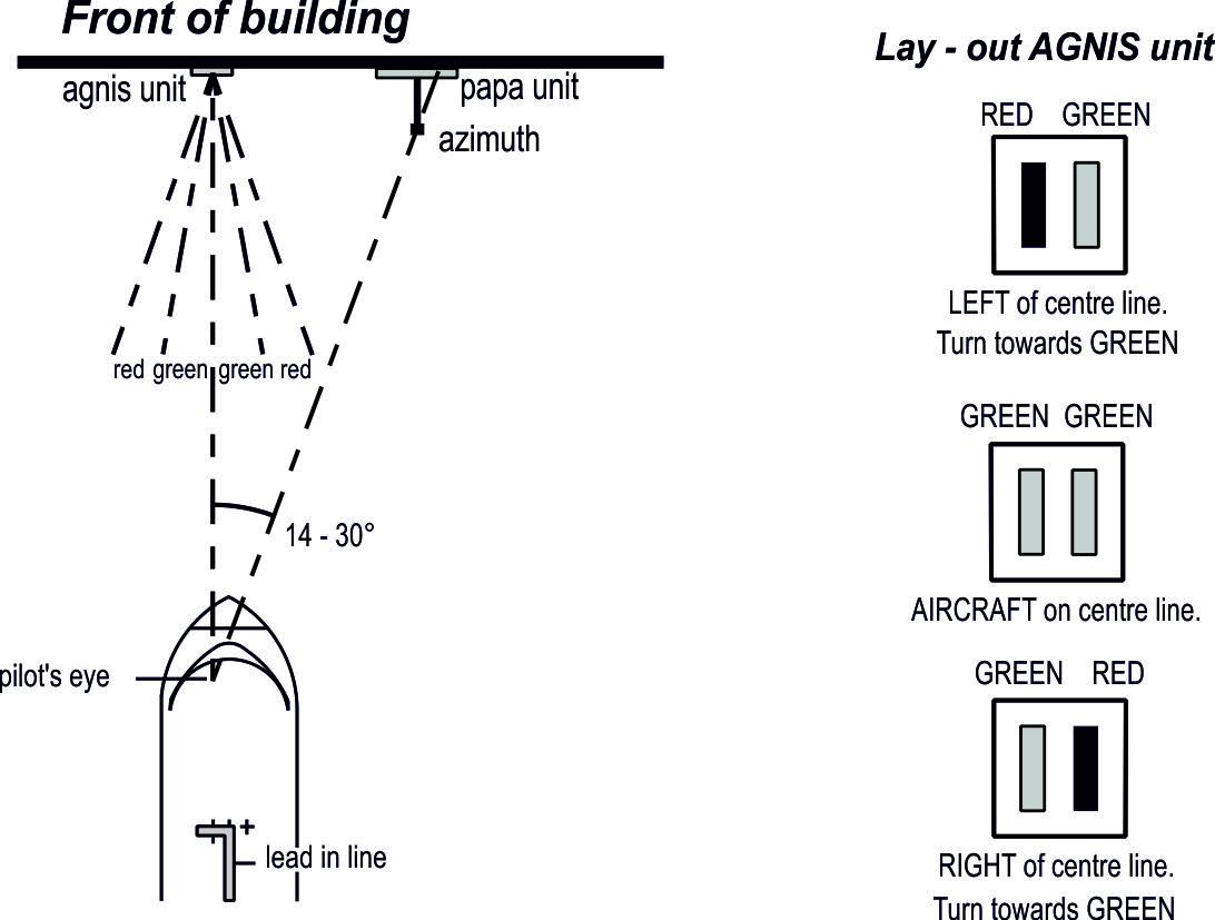
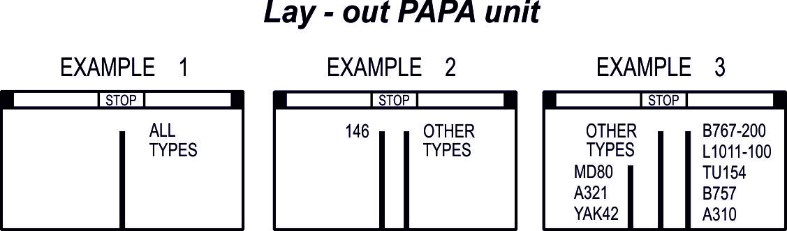
Self parking is applicable at the following aircraft stands:
During low visibility phase C and D, see AD 2.22 paragraph 3, marshaller guidance is required.
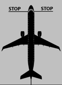
Extended stop line marking is provided on both sides of the lead-in line, provided with a yellow STOP marking on both extremes.
The STOP position is reached when the STOP marking is in line with the pilot’s eye view at an angle of 90 degrees to the lead-in line, see figure below.
The use of auxiliary power units (APU) and ground power units (GPU) is strictly controlled at all aircraft stands where (fixed) 400 Hz power units or GPU are available. These power units shall be used to reduce environmental and noise burden.
For cooling and heating purposes (zero emission) pre-conditioned air units (PCA) shall be used.
At all other aircraft stands, flight crew are urgently requested to not use the APU.
For cooling and heating purposes (zero emission) pre-conditioned air units (PCA) shall be used.
At all other aircraft stands, flight crew are urgently requested to not use the APU.
Exceptions:
- When it is necessary to use an APU to diagnose and/or rectify aircraft faults (for technical/maintenance reasons). Prior permission required from the Airside Operations office.
- When 400 Hz power units (including GPU) and/or PCA units are not operative or not available. Prior permission required from the Airside Operations office.
- When the outside temperature is below -5°C or above +25°C (according to METAR).
- PCA will not be connected in wind conditions from 36 KT (according to METAR) due to risk of equipment damage and/or injury. For specific PCA hoses with lesser mass a lower limit of 21 KT (according to METAR) applies.
- If a flight is subject to a 100% customs check and connection of a PCA is not allowed by the authorities.
- When it is necessary to use the APU to ensure safety on board (captain responsibility). Report to Airside Operations office as soon as practicable.
For contacting Airside Operations office: TEL +31 (0)20 601 2115.
Note
: Groundcontrol, Apron Control and channel 130.480 are not to be used.
Note : the use of aircraft engines for air-conditioning purposes on the apron is not allowed.
Note : the use of aircraft engines for air-conditioning purposes on the apron is not allowed.
Pilots are to use the minimum power necessary when manoeuvring on the taxiway system. This is of particular importance at locations where jet blast can affect adjacent aircraft stands such as:
Note:
when taxiing out on TWY A14 to TWY A or B, avoid turning left towards TWY A16 to avoid jet blast on aircraft stands E17 and E19.
Note:
when facing east on TWY A12, avoid turning left onto TWA A to avoid jet blast on aircraft stand E77.
- TWY A when turning left onto TWY S6 for line-up RWY 24 (ICAO code letter E and F aircraft only).
- TWY A when turning left onto TWY S7 for line-up RWY 24 or crossing RWY 24.
- TWY A9C when taxiing out on TWY A9C.
- TWY A10 when turning right onto TWY A13.
- TWY A12 when turning right onto TWY A13.
- TWY A16 when turning right onto TWY A.
- Aircraft stands D3, E18, E20, and E22 when docking.
Training flights and test flights from/to Schiphol Airport are only permitted MON-FRI daily 0600-2100 (0500-2000), but not on public holidays (see GEN 2.1). However, the following test flights are exempted from these restrictions:
These two exemptions are also permitted on SAT, SUN and public holidays daily 0800-1800 (0700-1700), provided they have permission of the Operational Helpdesk (in conformity with the standard procedure, see ENR 1.3).
All training and test flights must be co-ordinated 24 HR in advance with:
Furthermore, all training and test flights must have obtained, in advance, the explicit permission of the Flow Manager Aircraft of Amsterdam Airport Schiphol, TEL: +31 (0)20 601 2115.
All training and test flights must be co-ordinated 24 HR in advance with:
| Post: | LVNL
Operational Helpdesk P.O. Box 75200 1117 ZT Luchthaven Schiphol |
| Tel: | +31 (0)20 406 2201 (OPR HR: 0600-1600 (0500-1500)) |
| Email: | [email protected] |
| URL: | https://www.lvnl.nl/ohd |
It is not allowed to perform training flights with military aircraft.
The use of RWY 04/22 for training flights is only allowed for single engine propeller aircraft with an MTOM < 5700 KG (JAR-OPS category B). The use of a non-preferential runway for other training flights is not allowed.
No authorisation for carrying out ILS operations at Schiphol is required for foreign operators in possession of a declaration of competency issued by their national administrations.
Remote holding procedures may be used by ATC or the airport authority if:
A remote holding position must be entered via the standard taxi routing unless instructed otherwise by ATC. Pilots must stop at the indicated STOP position (see paragraph 10.3), to ensure sufficient clearance to adjacent taxiways. A departing aircraft will be towed to the remote holding position (see paragraph 10.4).
After ATC instruction the remote holding position must be vacated without delay, via the standard taxi routing unless instructed otherwise by ATC.
In order to optimise gate utilisation, aircraft which are ready for start-up may be repositioned onto another aircraft stand (see paragraph 10.5 and 10.6). This can either be initiated by the airport authority or on request of the ground handling company. The flight crew will be notified of the repositioning by the ground handling company, including the estimated holding duration.
After ATC instruction the remote holding position must be vacated without delay, via the standard taxi routing unless instructed otherwise by ATC.
In order to optimise gate utilisation, aircraft which are ready for start-up may be repositioned onto another aircraft stand (see paragraph 10.5 and 10.6). This can either be initiated by the airport authority or on request of the ground handling company. The flight crew will be notified of the repositioning by the ground handling company, including the estimated holding duration.
The following apron positions are available for remote holding:
| Apron | Location | Positions | Max wingspan | Remarks |
| P-holding | Between TWY A12 and TWY A13 | P1 | 69 M | Either P1 AVBL or PA and PB AVBL.
Either P3 AVBL or PC and PD AVBL. |
| P2 | 36 M | |||
| P3 | Not applicable | |||
| PA, PB, PC, PD | 36 M | |||
| On R-apron | Adjacent to TWY R | P20 | 36 M | Enter via TWY R.
Centre line and designated stop position not lighted 1). |
| P21 | 36 M | |||
| Adjacent to TWY Q and TWY R | P22 | 36 M | Enter via TWY A or TWY Q and P23.
Centre line and designated stop position not lighted. |
|
| P23 | 36 M | Enter via TWY A or TWY Q.
Exit via P22. Centre line and designated stop position not lighted. |
||
| On TWY VS | East of holding RWY 36L | P6 | Not applicable | Either P6 AVBL or
P6A and P6B AVBL. |
| P6A | 36 M | |||
| P6B | 36 M | |||
| P7 | Not applicable | Either P7 AVBL or
P7A and P7B AVBL. |
||
| P7A | 36 M | |||
| P7B | 36 M |
1)At the end of the combined lead-in line of remote holding position P20 and P21 pilots shall turn 180 degrees left for P20, or 180 degrees right for P21 to hold nose out at the designated stop position.
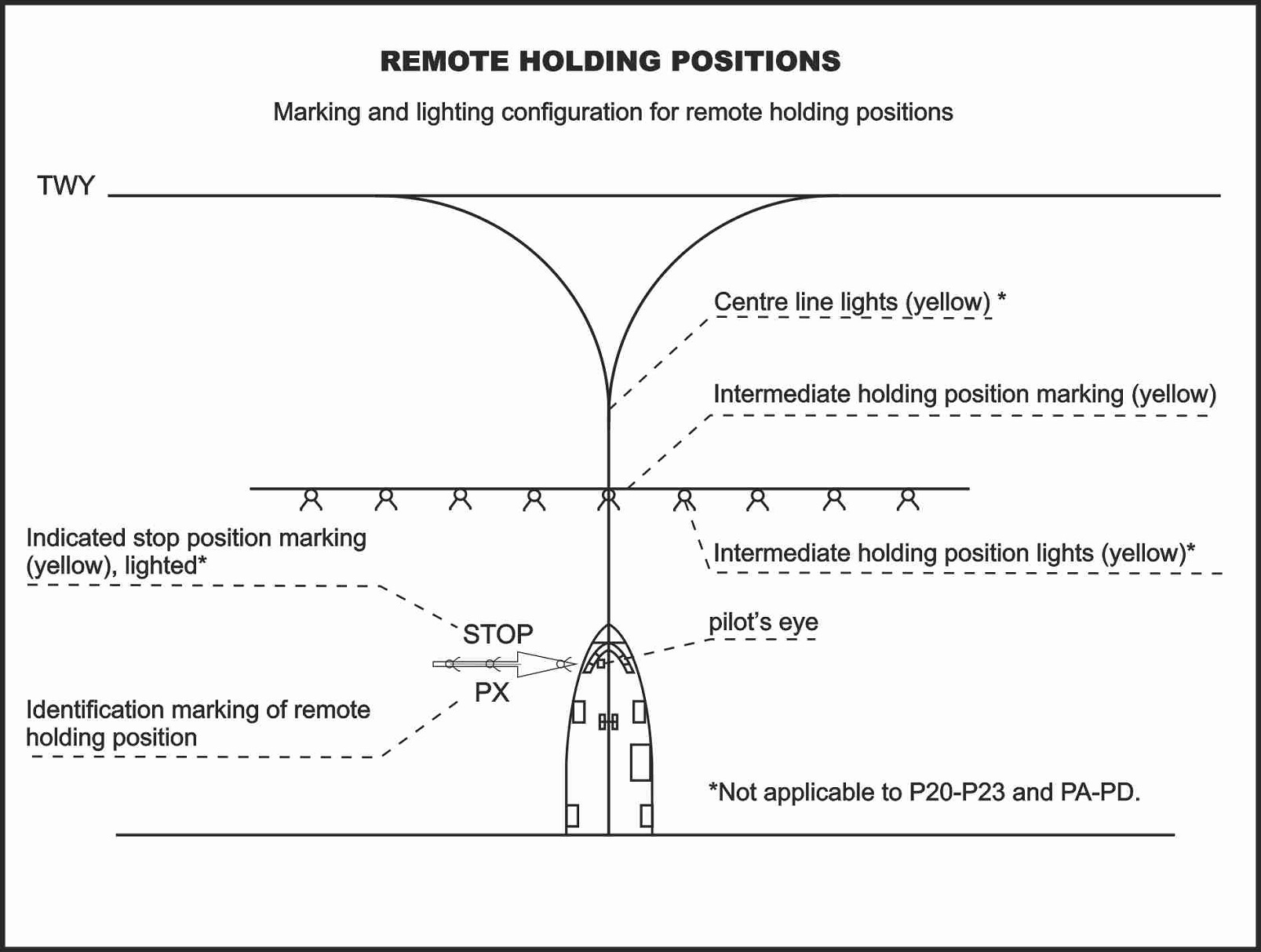
- Anti-collision lights remain switched on.
- Flight crew activates the transponder with the transponder code received from Schiphol Delivery.
- Flight crew contacts Schiphol Planner and confirms positioned at the remote holding position.
- Schiphol Planner will confirm transponder on radar and will instruct flight crew to monitor Schiphol Ground (monitor Schiphol Planner on the second communication set for possible reclearances).
- Flight crew instructs the truck driver to disconnect and awaits the "ALL CLEAR" signal from ground crew.
- Engines remain switched off; no prior approval required to use the APU.
Note:
see paragraph 9.6 for towing to aircraft stand G71.
- Anti-collision lights switched off, to be switched on just prior to push-back.
- Tow truck remains connected.
- Flight crew contacts Schiphol Planner and confirms positioned at the new aircraft stand.
- Engines remain switched off; no prior approval required to use the APU.
- Flight crew contacts Schiphol Planner in TSAT window.
Non KLM de-icing customers will be instructed by their specific ground handling company, see EHAM AD 2.23. KLM de-icing customers will be instructed by Snowdesk, see Snowdesk de-icing procedures below.
Note:
- Tactile checks must be performed at the gate/aircraft stand.
- Technical de-icing (landing gear, brakes, inside LE- or TE-flaps, under wing, engine inlets, fan blades, sensors and static ports/pitot probes) requires de-icing at the gate/aircraft stand, supervised by an aircraft maintenance technician (AMT). The aircraft operator is responsible for providing an AMT. If a regular de-icing treatment is still required afterwards, coordinate this with your ground handling company or Snowdesk, whichever is applicable.
- Contact Snowdesk at earliest opportunity by ACARS (preferential) or voice for de-icing request. Additional requests (e.g. fuselage de-icing) should be made on initial contact. Inform Snowdesk immediately when de-icing is not required anymore.
- Request ATC clearance from 20 MIN before TOBT or 35 MIN before CTOT.
- Snowdesk will assign remote de-icing at the J-apron. In case gate/aircraft stand de-icing is assigned, flight crew will specifically be informed as such by Snowdesk via VHF.
- Monitor Snowdesk as well as Schiphol Planner for any changes in the de-icing planning, until the ready call to Schiphol Planner is made.
- Report READY:
The following apron positions are available for remote de-icing:
- Taxiway A between TWY A19 and A20 may be used as holding position for de-icing operations at the J-apron. Avoid holding on the upslope between A19 and A20 to prevent unintentional backward movement of the aircraft. High power settings may cause jet blast damage. Advise ATC if unable to comply with taxi clearances.
- On taxiway A20 pilots shall use minimum breakaway thrust when turning right onto P10, P12, P14 and P16 to avoid jet blast hazard at adjacent aircraft stands.
- The J-apron, including adjacent TWY A20, is not controlled by ATC. Pilots shall maintain separation from other aircraft at their own discretion. Padcontrol is responsible for sequencing and spot assignment only.
- Pilots shall monitor Schiphol Ground at all times.
When instructed by Schiphol Ground, contact Padcontrol with call sign. Follow Padcontrol instructions and continue with the signboard procedure below. If Padcontrol indicates the signboards to be U/S, continue with the voice only procedure below.
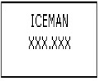
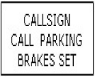
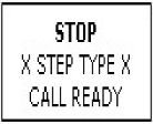
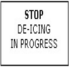
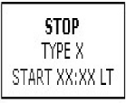
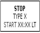
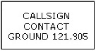
- When instructed by Padcontrol, contact Iceman with aircraft registration.
- Iceman will instruct: "ENTER (P10, P12, …)".
- Hold position, monitor Iceman COM channel for current treatment, anti-icing code and start time.
- Hold position until Iceman gives the "ALL CLEAR" signal.
- Cockpit preparations and flight control checks may now be performed.
- Iceman will advise when clear and to contact Schiphol Ground for taxi.
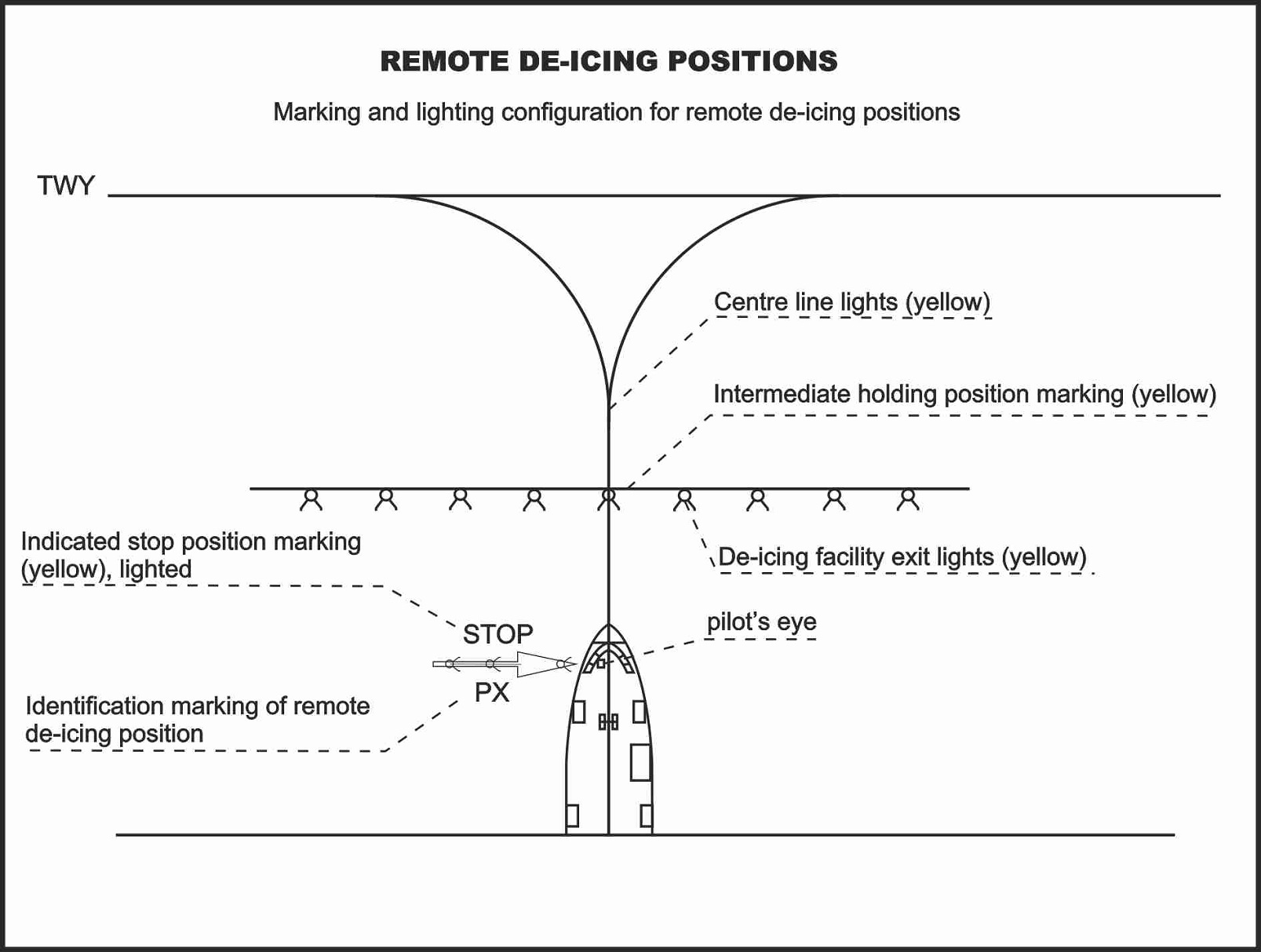
The J-apron, including adjacent TWY A20, is not controlled by ATC. Pilots shall maintain separation from other aircraft at their own discretion. Procedures for entering and leaving the J-apron are detailed below, for de-icing procedures at the J-apron refer to paragraph 11.
ATC instructs pilots entering the J-apron at TWY A20 to contact Apron Control 121.880 and follow the marshaller to the allocated aircraft stand.
- Contact Schiphol Planner for start-up approval.
- If parked at aircraft stand P10, P12, P14 or P16 and facing TWY A, contact Schiphol Ground for taxi clearance.
- In all other situations, including aircraft parked at aircraft stand J80 - J87, contact Apron Control (121.880) to reposition the aircraft near the ATC service boundary on TWY A20.
- Hold at the ATC service boundary on TWY A20 and contact Schiphol Ground (121.905) for taxi instructions.
The K-apron is not controlled by ATC; ground handling companies (see EHAM AD 2.23) handle the aircraft and allocate aircraft stands. The K-apron is open H24, for operating hours ground handling companies see EHAM AD 2.3. For aircraft stands and wingspan restrictions see chart APDC Schiphol East K-apron.
Pilots shall enter the K-apron via intermediate holding position GL.
- At intermediate holding position GL, contact Schiphol Amsterdam General Aviation (121.930) for aircraft stand allocation.
- Self parking on all aircraft stands; nose in parking is mandatory. Contact ground handler if assistance is required.
- A 180° turn using aircraft thrust is prohibited on all aircraft stands; aircraft will be turned by tow truck.
Pilots shall leave the K-apron via intermediate holding position GD.
Note:
- IFR flights contact Schiphol Planner for start-up approval; VFR flights contact Schiphol Delivery for start-up approval.
- Contact Schiphol Amsterdam General Aviation (121.930) to obtain approval to taxi to intermediate holding position GD.
- Hold at intermediate holding position GD and contact Schiphol Ground (121.805) for further taxi instructions.
- Taxiing is only allowed after the "ALL CLEAR" signal from the ground crew;
- Taxiing from aircraft stand must commence within one minute after approval by Schiphol Amsterdam General Aviation;
- When leaving aircraft stands K20 - K28 and K35 - K38 low power setting is required to avoid possible jet blast on adjacent aprons and service roads;
- Exiting the K-apron via intermediate holding position GL is prohibited.
| Reference | Deviation | Related AIP section |
| 1 | 2 | 3 |
| Runway turn pads | ||
| CS ADR-DSN.B.095 | A runway turn pad is not provided at the end of RWY 24. Instead, a turn-around area is provided. | EHAM AD 2.23 |
| Taxiways general | ||
| CS ADR-DSN.D.240 (a) | On several locations, the minimum wheel clearance for aircraft with outer main gear wheel span between 9 and 15 M is not AVBL. | EHAM AD 2.8 |
| Taxiway minimum separation distance | ||
| CS ADR-DSN.D.260 (b) | On several locations, the minimum separation distance between aircraft and obstacles is not AVBL for aircraft with wingspan of 65 M or more. | EHAM AD 2.8 |
| Longitudinal slopes on taxiways | ||
| CS ADR-DSN.D.265 (b)(1) | At TWY A1A the longitudinal slope locally exceeds 1.5%. | EHAM AD 2.8 |
| Sight distance of taxiways | ||
| CS ADR-DSN.D.275 (b)(1) | For some smaller code letter C aircraft a sight distance less than 300 M applies at the taxiway bridge TWY A - Q. | EHAM AD 2.8 |
| Rapid exit taxiway | ||
| CS ADR-DSN.D.295 | The radii of the rapid exit taxiways vary between 300 and 550 M. | EHAM AD 2.12 |
| Taxiways on bridges | ||
| CS ADR-DSN.D.300 (c) | No straight TWY section has been provided prior to the TWY bridge connecting TWY V and TWY Y and vice versa, connecting TWY Z to TWY V and connecting TWY W13 to TWY V. | EHAM AD 2.8 |
| Objects on taxiway strips | ||
| CS ADR-DSN.D.320 | A frangible object with limited height is present within the taxiway strip of the curve of TWY B - Q. | EHAM AD 2.8 |
| CS ADR-DSN.D.320 (b)(1) | In the curve of TWY A and Q a lateral restraint is placed at the edge of the taxiway pavement. | EHAM AD 2.8 |
| Slopes on taxiway strips | ||
| CS ADR-DSN.D.330 (b)(c) | The maximum allowable slope of 5% is exceeded near taxiway bridges. | EHAM AD 2.8 |
| Runway holding position on a taxiway | ||
| CS ADR-DSN.D.335 | Runway holding positions Z1, Z2, Y1 and Y2 are positioned within the obstacle limitation surfaces of RWY 18C/36C. | EHAM AD 2.9 |
| Holding bays, runway holding positions, intermediate holding positions, and road holding positions | ||
| CS ADR-DSN.D.335 (b)(1) | Runway holding positions to protect the obstacle limitation surfaces of RWY 09/27 are not provided on TWY C and D. | EHAM AD 2.9 |
| Location of holding bays, runway holding positions, intermediate holding positions and road holding positions | ||
| CS ADR-DSN.D.340 | For code letter F operations, the location of runway holding positions for code letter E operations are used. | EHAM AD 2.9 |
| Clearance distances on aircraft stands | ||
| CS ADR-DSN.E.365 | On several aircraft stands, the clearance distance for aircraft with wingspan of 36 M or more is less than 7.5 M. | EHAM AD 2.8 |
| CS ADR-DSN.E.365 (b) | At aircraft stands A41 and A51 the clearance distance between the wingtip and the service road is less than 4.5 M for code letter C aircraft. | EHAM AD 2.9 |
| Wind direction indicator | ||
| CS ADR-DSN.K.490 (b) | On several runways, wind direction indicators are only AVBL at the beginning of the runway. | NIL |
| Markings General – Colour and conspicuity | ||
| CS ADR-DSN.L.520 (b) | For taxiway centre line markings of taxiways A19E and A19W, alternative colours are used. | EHAM AD 2.9 |
| Runway designation marking | ||
| CS ADR-DSN.L.525 (c)(1)(i) | The renumbering of the RWY designator of RWY 09/27 has been formally postponed by the competent authority until 2030. | EHAM AD 2.12 |
| Threshold marking – Displaced threshold | ||
| CS ADR-DSN.L.535 (c)(3) | The distance between the last arrow marking and the threshold marking of RWY 18L is 27 M instead of 20 M. | EHAM AD 2.9 |
| Taxiway centre line marking | ||
| CS ADR-DSN.L.555 (b)(5) | At two specific locations (prior to TWY-RWY intersection E1 and on TWY N2, prior to connecting to RWY 09/27) the taxiway centre line markings are interrupted in the curves leading towards the respective runways to prevent a runway incursions. | EHAM AD 2.9 |
| Interruption of runway markings | ||
| CS ADR-DSN.L.560 (c) | At two specific locations (N2/E6 across RWY 09/27 and S7W/S8 across RWY 06/24) the taxiway centre line marking continues across the total width of the runway. | EHAM AD 2.9 |
| Aircraft stand markings | ||
| CS ADR-DSN.L.590 | Guidance between taxiway CL and lead-in lines is interrupted over a length of APRX 15 M. | EHAM AD 2.9 |
| CS ADR-DSN.L.590 (f)(2) | Stop lines at self-docking aircraft stands are located at equal distance left and right of the lead-in line. | EHAM AD 2.9 |
| CS ADR-DSN.L.590 (f)(3) | Aircraft type markings are not used at Schiphol Airport. | EHAM AD 2.9 |
| Road holding position marking | ||
| CS ADR-DSN.L.600 (b)(2) | Road holding position markings along TWY S, designated for code letter F aircraft, are located at 43.5 M from the TWY centre line although TWY S is used by code letter F aircraft. | NIL |
| Mandatory instruction marking | ||
| CS ADR-DSN.L.605 (b)(2) | TWY G3 and W6, no-entry markings are located across the taxiway instead of on both sides of the TWY CL marking. | EHAM AD 2.9 |
| CS ADR-DSN.L.605 (c)(1) | The text of the mandatory instruction markings at Z1, Z2, Y1 and Y2 is not ‘identical’ to the respective signs. | EHAM AD 2.9 |
| Precision approach category II and III lighting system | ||
| CS ADR-DSN.M.635 (a)(1) | The array of the APCH LGT 27 has a reduced length of 750 M. | EHAM AD 2.14 |
| CS ADR-DSN.M.635 (a)(2) | The interval between centre line lights of cat II/III approach lights of RWY 06 and 36R locally exceeds 30 M. | EHAM AD 2.9 |
| Precision approach path indicator and abbreviated precision approach path indicator (PAPI and APAPI) | ||
| CS ADR-DSN.M.645 (b)(4) | All PAPI units, except those serving RWY 09, RWY 18R and RWY 27, are located further than the required 15 M from the edge of the full strength runway
pavement. |
EHAM AD 2.14 |
| Runway edge lights | ||
| CS ADR-DSN.M.675 (b)(4) | RWY 04/22: irregular interval between edge LGT at intersection with TWY G3. | EHAM AD 2.9 |
| Taxiway centre line lights | ||
| CS ADR-DSN.M.710 (b)(1) | Lead-in lights to aircraft stands are not AVBL. | EHAM AD 2.9 |
| CS ADR-DSN.M.710 (c)(1) | For taxiway centre line lights of taxiways A19E and A19W, alternative colours are used. | EHAM AD 2.9 |
| Intermediate holding position lights | ||
| CS ADR-DSN.M.735 (b) | At VL and VM intermediate holding position lights are co-located with the respective markings. | EHAM AD 2.9 |
| CS ADR-DSN.M.735 (c)(1) | At VL and VM intermediate holding position lights radiate bi-directional light. | EHAM AD 2.9 |
| Runway guard lights | ||
| CS ADR-DSN.M.745 (b)(1) | Runway guard lights are only provided at hotspots. | EHAM AD 2.9 |
| Road holding position light | ||
| CS ADR-DSN.M.770 (a) | Road holding position lights are not provided. | NIL |
| Information signs | ||
| CS ADR-DSN.N.785 (a)(11) | On several locations, location signs are not provided in conjuction with direction signs. | EHAM AD 2.9 |
| CS ADR-DSN.M.785 (b)(2) | Information signs are sometimes located within the minimum required 60 M distance from the intersecting taxiway. | EHAM AD 2.9 |
| CS ADR-DSN.M.785 (b)(3) | Runway exit signs are located further than the required 8-15 M from the edge of the full strength runway pavement. | EHAM AD 2.9 |
| CS ADR-DSN.N.785 (c)(9) | Intermediate holding positions VK, VL and VM have a two-letter designator instead of a progressive number. | EHAM AD 2.9 |
| Aircraft stand identification signs | ||
| CS ADR-DSN.N.795 (c) | On several aircraft stands, the aircraft stand identification signs consist of a inscription in yellow on a black background. | EHAM AD 2.9 |
| Lighting of fixed objects with a height 45 M to a height less than 150 M above ground level | ||
| CS ADR-DSN.Q.848 (a) | Obstacle lights on the central air traffic control tower are low intensity lights. | EHAM AD 2.10 |
| Electrical systems – monitoring | ||
| CS ADR-DSN.S.890 (d) | Aeronautical ground lights are not monitored fully automatic. | NIL |
| CS ADR-DSN.S.890 (e) | No full warning of aeronautical ground lights malfunction is sent to ATS unit. | NIL |
| Siting of equipment and installations on operational areas | ||
| CS ADR-DSN.T.915 (b)(1) | Several objects within the taxiway strips do not serve the purpose of air navigation or aircraft safety. | NIL |
The following departure and arrival procedures have proved to be highly efficient in respect of noise abatement in the vicinity of Schiphol Airport. Aircraft may deviate from these procedures for safety reasons or otherwise instructed by ATC.
The use of the noise abatement take-off and climb procedure NADP2 as mentioned in ICAO Doc 8168 Volume III is recommended for all jet aircraft departures from Schiphol Airport. If for operational reasons compliance with the recommended procedure is not possible, NADP1 may be used, but it is imperative to inform Schiphol Delivery if unable to comply with NADP2 as soon as possible via RTF. Adherence to this procedure is automatically monitored.
Note:
operators are requested to inform the airport authority on the details of their departure procedure by sending copies of the relevant pages of the aircraft operating manual (AOM) to:
| Post: | Amsterdam Airport Schiphol
Corporate Development Strategy & Airport Planning P.O. Box 7501 1118 ZG Schiphol Airport The Netherlands |
|
| Email: | [email protected] |
The standard instrument departure routes as contained in EHAM AD 2.22 paragraph 1.5 avoid residential areas as much as possible and must be considered minimum noise routes.
For RWY 06 and RWY 18R RNAV low-noise procedures, continuous descent approach (CDA), for jet aircraft will be used between 2130-0530 (2030-0430), otherwise aircraft will be radar vectored towards interception of final leg at 3000 FT AMSL. Executing a CDA implies that after NIRSI, NARIX or SOKSI a continuously descending flight path without level segments is to be flown in a low power and low drag configuration. A flight path is considered continuously descending when there is no level segment. A segment is considered level if the altitude loss is less than 50 FT over a distance of 2.5 NM. For procedures and exemptions see EHAM AD 2.22 paragraph 2.7.2.
For noise abatement using a reduced flaps landing procedure is recommended. However, use of this procedure is subject to captain's decision and safety prevails at all times.
Note:
operators / aircraft types, not able to comply with the mentioned landing procedure, are requested to inform the airport authority by sending copies of the landing procedure in use to:
| Post: | Amsterdam Airport Schiphol
Corporate Development Strategy & Airport Planning P.O. Box 7501 1118 ZG Schiphol Airport The Netherlands |
|
| Email: | [email protected] |
- Intercept the final leg, avoiding populated areas as much as possible.
- Follow a descent path using a minimum flap setting with landing gear retracted which will NOT be lower than 5.2% (3.0 degrees).
- Select gear down after passing 2000 FT AMSL.
- Postpone the selection of the minimum certified landing flap setting until passing 1200 FT AMSL.
The most frequently used runways are:
In unusual circumstances, such as extreme wind conditions, runways not available and during peak hours other choices may be used. Outside peak hours and during the night period a combination of 1 departure runway and 1 landing runway will be assigned. During outbound peak hours a combination of 2 departure runways and 1 landing runway may be in use. During inbound peak hours a combination of 1 departure runway and 2 landing runways may be in use. Assignment of runways in use is based on the
preferential runway system
, as prescribed in paragraph 4.3. For VFR traffic normally the RWY 04/22 will be assigned.
Note:
propeller driven aircraft may be assigned a different departure and landing runway.
Note:
the attention of pilots on final of RWY 04 or 22 is drawn to the size and texture of the parallel taxiway which, under certain weather conditions, is more conspicuous than the runway.
The helispot can be used by helicopters arriving at or departing from Schiphol-East and is in principle only available during the night hours. A minimum altitude of 150 FT applies in the sectors between 105° - 165° MAG and 245° - 345° MAG.
The runways in use at Schiphol Airport will be selected by ATC according to a preferential runway system. This system is based on the following principles:
Due to noise abatement considerations, the use of a non-preferential runway for take-off and for landing is not permitted unless specifically requested for safety reasons by the pilot.
However, if a pilot decides that a different landing runway should be used for safety reasons, ATC will assign that runway (air traffic and other conditions permitting). Deviations from the preferential sequence for selecting runways in use can be made by ATC:
- traffic safety prevails at all times.
- departure and landing will normally take place on separate runways.
- preferably a runway equipped with ILS will be selected for landing.
- the preferential sequence for selecting runways in use depends on the combination of noise influences and traffic handling.
-
the wind and visibility criteria are directives for the selection of the runway combination(s) from the preferential sequence. These
directives are in accordance with the guidance material laid down in Annex 16-ICAO (Aircraft noise). - deviations from an assigned runway in order to obtain a shorter taxi route, departure or approach pattern are not permitted.
However, if a pilot decides that a different landing runway should be used for safety reasons, ATC will assign that runway (air traffic and other conditions permitting). Deviations from the preferential sequence for selecting runways in use can be made by ATC:
- when approach facilities on the selected runway are not suitable for operations in the prevailing weather.
- when crosswind components do not meet the given limits for any runway combination.
- when estimated surface friction on runways is below certain standards.
- when heavy showers are observed or wind shear is reported in the vicinity of the airport.
The preferential sequence for selecting runways in use is being determined by the Airport Authority in close co-operation with ATC. This preferential sequence is subject to noise load developments. Therefore the preferential sequence for selecting runways may change in any given period.
In selecting the runway combination to be used from the preferential runway system, LVNL also applies wind speed criteria. In applying these wind criteria, gusts below 10 KT shall not be taken into account. Accepting a runway is a pilot's decision. If a pilot, prompted by safety concerns, requests another runway for landing, this request will be granted when possible. In that case, the pilot must submit a written report (the operator is responsible for proper reporting procedures).
- RWY 18R is not available for departures and RWY 36L is not available for arrivals.
- RWY 36R is not available for departures and RWY 18L is not available for arrivals.
- From 2130-0530 (2030-0430) RWY 04/22 is not available for departures and arrivals.
- From 2130-0530 (2030-0430) RWY 09/27 is not available for departures and arrivals.
- From 2130-0530 (2030-0430) RWY 18C is not available for arrivals and RWY 36C is not available for departures.
- From 2130-0530 (2030-0430) RWY 18L is not available for departures.
- From 2130-0530 (2030-0430) RWY 24 is not available for arrivals.
- From 2130-0530 (2030-0430) RWY 36R is not available for arrivals.
Between 2030-0530 (1930-0430): After landing, the use of idle reverse thrust is advised on all runways except RWY 04/22, safety permitting. To achieve the highest possible runway capacity, runway occupancy times are to be reduced to a minimum.
- Take-off and landing is not allowed for aircraft which are certified in accordance with the noise standards of ICAO Annex 16 Chapter 2.
-
For aircraft certified in accordance with the noise standards of ICAO Annex 16 Chapter 3, for which the margin of the sum of the three certification noise levels, relative to the sum of the three applicable ICAO Annex 16 Chapter 3 certification noise limits, is less than 10 EPNdB, the following applies:
- New operations are not allowed.
- For aircraft equipped with engines with bypass ratio <= 3, take-off and landing is not allowed between 1700-0700 (1600-0600).
- For propeller-driven aircraft, and aircraft equipped with engines with bypass ratio > 3, it is not allowed to plan take-off between 2200-0600 (2100-0500).
The instrument departure procedures are based on ICAO Annex 2 and on ICAO Documents 4444-ATM/501 (PANS-ATM), 7030 (SUPPS) and 8168-OPS/611 (PANS-OPS). The procedures are developed with a view to make optimum use of the available airspace. It is therefore essential that pilots navigate in compliance with these in-flight procedures with the highest possible accuracy. See GEN 1.5 for required RNAV equipment in the Schiphol TMAs.
Executive control of traffic en-route and in the Schiphol TMAs is exercised by radar controllers. For operational use of radar see ENR 1.6.
Executive control of traffic in the Schiphol TMAs is exercised by radar controllers. During the peak hours outbound traffic will be handled by a TMA-west controller (Schiphol Departure 121.205) and a TMA-east controller (Schiphol Departure 119.055). Outside peak hours one radar controller is responsible for the provision of approach/departure control service in the Schiphol TMA on both channels simultaneously.
En-route clearance shall be requested to Schiphol Delivery MAX 20 minutes prior to EOBT or 35 minutes prior to CTOT. If RWY 36L is used, clearance shall be requested MAX 30 minutes prior to EOBT or 45 minutes prior to CTOT. An en-route clearance contains:
Example of an en-route clearance: "KLM3274 cleared to Paris, FL 60, KUDAD 3S Departure, runway 24, squawk 2123, slot 25".
En-route clearance is issued by means of a datalink departure clearance (DCL) service.
Request the clearance from Schiphol Delivery via RTF when:
The implementation of the DCL service is based on EUROCAE Document ED-85. The following procedure applies:
When using the DCL service pilots shall maintain a listening watch on the channels published for clearance delivery. Prior to departure, both the pilot and the air traffic controller shall verify that the departure route assigned via the DCL service logically refers to the runway used and to the route indicated in the current ATC flight plan. In the event of any doubts or system related difficulties, RTF procedures shall be resumed. An en-route clearance issued by RTF always supersedes an en-route clearance transmitted via the DCL service.
After en route clearance is obtained and either read back via RTF or confirmed via datalink, pilots shall immediately (without ATC instruction) select and monitor Schiphol Planner.
Note:
the instrument departure procedures are laid down in standard instrument departures (SIDs). SIDs are designated in accordance with ICAO Annex 11. SID designation is composed of the following elements:
Note:
if not able to comply with the crossing conditions prescribed in the SIDs, inform Schiphol Delivery as soon as possible.
Note
: if not able to comply with the noise abatement take-off and climb procedure NADP2, it is imperative to inform Schiphol Delivery as soon as possible via RTF.
Note:
additional departure instructions containing deviations from the SID may be added to the en-route or take-off clearance. These instructions may comprise an opposite turn after take-off, maintaining a specified heading or temporary altitude restrictions; these additional instructions amend the relevant part of the SID only.
Note:
during off-peak hours one clearance delivery/outbound planner may be active. In that case the channels will be combined by ATC.
Note:
information about expected runway combinations related to SIDs, during peak hours, is broadcasted on 131.355 (call sign "ATC Operational Information Schiphol").
En-route clearance is issued by means of a datalink departure clearance (DCL) service.
Request the clearance from Schiphol Delivery via RTF when:
- The pilot sends a request for en-route clearance downlink (RCD) at the above mentioned times.
- A flight system uplink message (FSM) will be transmitted automatically.
- The pilot shall acknowledge the en-route clearance by means of a departure clearance readback downlink (CDA) within 5 minutes; otherwise a negative FSM will be issued.
- When the CDA is processed successfully, a positive FSM will be issued to mark the end of the procedure.
After en route clearance is obtained and either read back via RTF or confirmed via datalink, pilots shall immediately (without ATC instruction) select and monitor Schiphol Planner.
A-CDM at Schiphol Airport is a joint initiative between the aircraft operators (AO), ground handlers, ATC and the airport. The key aims of A-CDM are to facilitate the sharing of operational processes and data to allow better informed decisions to be made. A-CDM facilitates the optimal handling of turn-around processes at the airport.
TOBT represents the time that the ground handler and the flight crew estimate an aircraft will be ready, with all ground handling activities finished, all doors closed, and the boarding bridge and handling equipment removed.
TSAT represents the time at which flight crew can reasonably expect start-up approval from ATC. It takes into account TOBT, CTOT (if applicable), variable taxi times (including de-icing, if applicable), current local traffic situation, applicable SID and wake turbulence separation. Push-back truck availability at stand is based on TSAT.
TOBT represents the time that the ground handler and the flight crew estimate an aircraft will be ready, with all ground handling activities finished, all doors closed, and the boarding bridge and handling equipment removed.
TSAT represents the time at which flight crew can reasonably expect start-up approval from ATC. It takes into account TOBT, CTOT (if applicable), variable taxi times (including de-icing, if applicable), current local traffic situation, applicable SID and wake turbulence separation. Push-back truck availability at stand is based on TSAT.
The ground handler sets an accurate TOBT. If an earlier departure is anticipated, or the TOBT can no longer be met, the flight crew must contact the ground handler as soon as possible to update the TOBT. TOBT adherence will be monitored and reported to the AO/ground handler.
Flight crew shall ONLY report ready to Schiphol Planner when:
This report shall include aircraft identification, parking position, ATIS information and the "READY" message. Failing to comply will result in an inaccurate push-back and runway planning, which may result in a loss of total usable runway capacity.
TSAT is displayed on most contact stands via VDGS or should be requested from the ground handler if no display is available. In case TSAT has expired, flight crew must contact the ground handler to set a new TOBT. TSAT expiry can result in extensive delay.
At push-back stands Schiphol Planner will give instructions to contact Schiphol Ground for start-up, push-back and taxi instructions.
At taxi-out stands Schiphol Planner will give start-up approval and instructions to contact Schiphol Ground for taxi instructions.
When instructed by Schiphol Planner, the flight crew shall directly contact Schiphol Ground and immediately comply with start-up, push-back and taxi permission. Since ATC planning of outbound traffic (involving en-route clearance and co-ordination with adjacent ACCs) is based on the start-up time, any delay shall be reported to ATC immediately.
Note:
With A-CDM every flight is RFI (request for improvement) continuously from EOBT-2 hours until TSAT-10 minutes. In case of a CTOT however, flight crew may additionally request Schiphol Planner to send a “READY” message for a possible CTOT improvement. Flight crew may only request Schiphol Planner to send a "READY" message under the following conditions:
Note:
In case one or more engines need to be started prior to push-back, flight crew must request permission accordingly with Schiphol Planner. The permission for start-up does not include permission for push-back. Push-back shall only be initiated after receiving the push-back clearance from Schiphol Ground (see paragraph 1.3.3).
Note:
VFR flights and flights with status HEAD and HOSP are exempted from reporting ready within TSAT window. Flight crew of these flights shall report ready to Schiphol Planner as soon as they are fully ready.
Note:
J-apron and K-apron are not under ATC ground control. At K-apron flight crews shall report to Schiphol Ground at apron exit GD.
Flight crew shall ONLY report ready to Schiphol Planner when:
TSAT is displayed on most contact stands via VDGS or should be requested from the ground handler if no display is available. In case TSAT has expired, flight crew must contact the ground handler to set a new TOBT. TSAT expiry can result in extensive delay.
At push-back stands Schiphol Planner will give instructions to contact Schiphol Ground for start-up, push-back and taxi instructions.
At taxi-out stands Schiphol Planner will give start-up approval and instructions to contact Schiphol Ground for taxi instructions.
When instructed by Schiphol Planner, the flight crew shall directly contact Schiphol Ground and immediately comply with start-up, push-back and taxi permission. Since ATC planning of outbound traffic (involving en-route clearance and co-ordination with adjacent ACCs) is based on the start-up time, any delay shall be reported to ATC immediately.
Ground control service (start-up, push-back and taxi instructions) is provided by Schiphol Ground (see EHAM AD 2.18 and GMC chart).
Pilots shall only ask for start-up and push-back permission after having confirmed that the ground crew is ready. The anti-collision light must be switched on just prior to push-back.
Cross bleed engine start at the aircraft stand is prohibited as well as performing a power-back using reverse thrust.
The flight crew is part of the communication chain between ground controller and truck driver. Therefore the use of a ground engineer with an intercom connection is recommended. When intercom connection with a ground engineer is not possible, the pilot shall inform Schiphol Ground.
The flight crew shall read back to ATC all instructions contained in the push-back clearance. The flight crew shall ensure that the complete push-back clearance from ATC is communicated word-for-word to the push-back crew.
Upon receiving start-up and push-back permission from Schiphol Ground, the aircraft shall move within 1 minute in order to ensure conflict free ground operations and maximum usage of ground capacity. If the 1 minute window is expired, the push-back permission will automatically expire and a push-back permission shall be requested again.
Upon completion of the push-back procedure the flight crew must wait for the "ALL CLEAR" signal on the taxiway before requesting a taxi clearance. Schiphol Airport has instructed ground handlers to give the "ALL CLEAR" signal distinctly. During hours of darkness illuminated wands will be used.
Pilots shall only ask for start-up and push-back permission after having confirmed that the ground crew is ready. The anti-collision light must be switched on just prior to push-back.
Cross bleed engine start at the aircraft stand is prohibited as well as performing a power-back using reverse thrust.
The flight crew is part of the communication chain between ground controller and truck driver. Therefore the use of a ground engineer with an intercom connection is recommended. When intercom connection with a ground engineer is not possible, the pilot shall inform Schiphol Ground.
The flight crew shall read back to ATC all instructions contained in the push-back clearance. The flight crew shall ensure that the complete push-back clearance from ATC is communicated word-for-word to the push-back crew.
Upon receiving start-up and push-back permission from Schiphol Ground, the aircraft shall move within 1 minute in order to ensure conflict free ground operations and maximum usage of ground capacity. If the 1 minute window is expired, the push-back permission will automatically expire and a push-back permission shall be requested again.
Upon completion of the push-back procedure the flight crew must wait for the "ALL CLEAR" signal on the taxiway before requesting a taxi clearance. Schiphol Airport has instructed ground handlers to give the "ALL CLEAR" signal distinctly. During hours of darkness illuminated wands will be used.


After taxi instructions have been obtained, departing aircraft shall take the shortest way to the main taxi route (see GMC and APDC chart).
Pilots may expect instructions to change ground control channel. Pilots shall not change channel without ATC instructions.
Note:
during off-peak hours one ground controller may be responsible for all areas. Ground control service will be provided on the 3 separate channels simultaneously. Therefore these channels will be combined by ATC.
Note:
during peak hours (normally when a second departure runway or a second landing runway is in use) 3 ground controllers may be active, each on their own channel.
Note:
during peak hours ground control service for traffic to and from RWY 18R/36L will also be provided by TWR-W (see GMC chart).
Note:
some runway crossings are safeguarded under all visibility conditions (see EHAM AD 2.9 item 3 "Stop bars" and GMC chart). At these positions crossing of activated stop bars is prohibited. Traffic may proceed only after ATC clearance and when the stop bar lights are switched off.
Pilots may expect instructions to change ground control channel. Pilots shall not change channel without ATC instructions.
- In principle all jet aircraft must use the full runway length available for noise abatement reasons.
- ATC may assign an intersection take-off to any aircraft for operational reasons (e.g. sequencing due to lack of holding area or to avoid jet blast on intersecting runways).
- Flights from S-apron departing from RWY 24 will be assigned intersection take-off TWY S8.
- During low visibility procedures intersection take-offs are not allowed. Take-offs from RWY 24 intersection TWY S6 and S8 may be allowed at ATC discretion (see EHAM AD 2.22 paragraph 3). If intersection TWY S6 is in use during low visibility procedures, intersection TWY S7E will not be used.
Converging departure and approach procedures may be in progress. To avoid conflicts with possible missed approaches:
- complete all cockpit checks before line-up;
- expedite line-up and start the take-off roll within 10 seconds after receiving the take-off clearance;
- in case an engine run-up on the runway is required, pilots shall inform Schiphol Tower at first contact.
When unable to comply with the above, inform ATC as soon as possible. The take-off clearance may be revoked.
- complete all cockpit checks before line-up;
- expedite line-up and start the take-off roll within 10 seconds after receiving the take-off clearance;
- in case an engine run-up on the runway is required, pilots shall inform Schiphol Tower at first contact.
Pilots of departing aircraft will be instructed by Schiphol Ground which channel they shall use. During peak hours air traffic in the vicinity of Schiphol Airport will be controlled by two tower controllers.
Note:
in addition to departing and arriving traffic, also aircraft crossing the runway and vehicles on the runway will have contact with the tower controller on the tower channel.
Note:
during peak hours air traffic services for departures from RWY 36L will normally be provided from TWR-W.
A jet blast hazard exists when the following runway combinations are in use:
| 1. | Departure RWY 18L and departure RWY 24: | ATC will time departures from RWY 24 to avoid jet blast on RWY 18L. |
| 2. | Departure RWY 18L from intersection TWY E5
and departure or landing RWY 09: |
ATC will time departures from RWY 18L to avoid jet blast on RWY 09. |
| 3. | Departure RWY 18L from intersection TWY E5
and departure or landing RWY 27: |
ATC will time departures from RWY 18L to avoid jet blast on RWY 27. |
| 4. | Departure RWY 24 and landing RWY 36R: | ATC will time departures from RWY 24 to avoid jet blast on RWY 36R. |
When the current surface wind speed is 20 KT or more, ATC shall inform pilots about the current surface wind direction and speed (including gusts >= 5 KT). When the current surface wind speed is less than 20 KT, ATC shall report this information only in case of significant changes in relation to the ATIS broadcast.
Wake turbulence separation is applied in accordance with the RECAT-EU departure separation, as described in the EUROCONTROL document 'RECAT-EU European Wake Turbulence Categorisation and Separation Minima on Approach and Departure'.
In addition to these separation minima for departures, a minimum of 80 seconds for a lower heavy (CAT C) behind an upper heavy (CAT B) is required at Schiphol Airport for safety reasons. On departure, when receiving line up clearance, the pilot must inform ATC if greater wake turbulence separation is required than the RECAT-EU minima specified in the table below. The requirements for minimum runway occupancy time apply (see paragraph 1.3.3.3).
In addition to these separation minima for departures, a minimum of 80 seconds for a lower heavy (CAT C) behind an upper heavy (CAT B) is required at Schiphol Airport for safety reasons. On departure, when receiving line up clearance, the pilot must inform ATC if greater wake turbulence separation is required than the RECAT-EU minima specified in the table below. The requirements for minimum runway occupancy time apply (see paragraph 1.3.3.3).
|
RECAT-EU TBS
[MIN:SEC] |
Follower | ||||||
|
Super heavy
(A) |
Upper heavy
(B) |
Lower heavy
(C) |
Upper medium
(D) |
Lower medium
(E) |
Light
(F) |
||
| Leader |
Super heavy
(A) |
- | 01:40 | 02:00 | 02:20 | 02:40 | 03:00 |
|
Upper heavy
(B) |
- | - | 01:20 | 01:40 | 02:00 | 02:20 | |
|
Lower heavy
(C) |
- | - | - | 01:20 | 01:40 | 02:00 | |
|
Upper medium
(D) |
- | - | - | - | - | 02:00 | |
|
Lower medium
(E) |
- | - | - | - | - | 01:40 | |
|
Light
(F) |
- | - | - | - | - | 01:20 | |
An additional 60 seconds will be applied to all the wake turbulence time-based separation minima described above when departing from an intermediate part of the same runway.
Note:
at Schiphol Approach/Departure, the distance based RECAT-EU separation applies as described in EHAM AD 2.22 paragraph 2.2.
Pilots of departing aircraft
shall remain on TWR channel until passing 2000 FT AMSL
. Contact Schiphol Departure as indicated below when passing 2000 FT AMSL and report altitude in order to verify SSR mode C (e.g. Schiphol Departure KLM 327, passing 2000 FT climbing FL 060 KUDAD 3S Departure).
Pilots shall select the proper departure channel (based on the SID route to the TMA boundary) as follows:
These channels are also named in the relevant SID description.
When changing channel from Schiphol Tower to Schiphol Departure, initial contact shall consist of SCHIPHOL DEPARTURE, CALL SIGN, actual ALTITUDE and SID. If a flight is cleared on a heading for initial departure, the heading shall be used instead of the SID. Additional instructions e.g. altitude restrictions shall also be mentioned on initial contact with Schiphol Departure.
When changing channel from Schiphol Tower to Schiphol Departure, initial contact shall consist of SCHIPHOL DEPARTURE, CALL SIGN, actual ALTITUDE and SID. If a flight is cleared on a heading for initial departure, the heading shall be used instead of the SID. Additional instructions e.g. altitude restrictions shall also be mentioned on initial contact with Schiphol Departure.
When changing channel from Schiphol Departure to Amsterdam ACC, initial contact shall consist of AMSTERDAM RADAR + CALLSIGN only. When a speed or heading has been assigned, this information shall be included in the initial call.
- If possible call Amsterdam ACC Supervisor on telephone number +31 (0)20 406 3999.
Note: use telephone connection to mitigate COM failure only. All telephone calls will be automatically recorded.
- If telephone connection is disconnected prematurely (before read-back), revert to general communication failure procedure (see ENR 1.3 paragraph "Communication Failure").
Additionally, for departing flights, the following communication failure procedure applies:
- If a clearance to climb or re-routing instructions have not been given, comply with the route and altitude limitations detailed in the allocated standard instrument departure procedure or the departure instructions provided at take-off until the last waypoint has been reached.
Note: use telephone connection to mitigate COM failure only. All telephone calls will be automatically recorded.
- If telephone connection is disconnected prematurely (before read-back), revert to general communication failure procedure (see ENR 1.3 paragraph "Communication Failure").
Additionally, for departing flights, the following communication failure procedure applies:
- If a clearance to climb or re-routing instructions have not been given, comply with the route and altitude limitations detailed in the allocated standard instrument departure procedure or the departure instructions provided at take-off until the last waypoint has been reached.
- Transition altitude: 3000 FT AMSL.
- Pilots of departing aircraft shall remain on TWR channel until passing 2000 FT AMSL . When passing 2000 FT AMSL change to the appropriate departure channel for the relevant SID and report altitude in order to verify SSR mode C by ATC.
- Flights with destination Rotterdam or Lelystad are exempted from flying SIDs within the Schiphol TMA.
- SIDs have to be considered as minimum noise routings.
- Initiate turns in due time in order not to overshoot radials.
- Turn radii based on a 25° bank angle.
- MAX 250 KIAS below FL 100 unless otherwise instructed. In case ATC allows/instructs to accelerate beyond 250 KIAS for operational purposes, the speed limitations on early SID turns (MAX 220 KIAS) remain applicable and shall be respected.
- For continuous routings and crossing conditions on ATS routes as applicable see paragraph 1.5.3.
Especially propeller-driven aircraft can expect additional departure instructions. These instructions may be added to the en route or take-off clearance and may comprise a specific heading or temporary altitude restriction. Such additives amend the relevant part of the SID only.
All SIDs require the use of RNAV routes stored in a pre-programmed navigation database on board of aircraft.
Furthermore:
Furthermore:
For some SIDs, differences in the way the coding for these SIDs is processed by the various FMS systems may result in considerable track dispersion during turns. This track dispersion can be reduced by the application of radius to fix turns, which results in concentration of the aircraft flight path. Thus in order to enhance noise abatement, for relevant SIDs RWY 24 an alternative coding comprising a radius to fix turn is introduced.
To distinguish between the standard coding and the coding comprising the RF turn the letter "Y" has been added after the SID identification. Consequently two ARINC contractions are listed for relevant SIDs. As an example, the ARINC contractions for the SPY 4K SID are given below:
In the ATC clearance, only the standard (unchanged) designator will be used without changes in the ATC clearance phraseology. This clearance allows for selection of either coding version as the resulting flight paths are considered identical by ATC.
For the use of the RF coding version the following requirements are applicable:
To distinguish between the standard coding and the coding comprising the RF turn the letter "Y" has been added after the SID identification. Consequently two ARINC contractions are listed for relevant SIDs. As an example, the ARINC contractions for the SPY 4K SID are given below:
For the use of the RF coding version the following requirements are applicable:
- The aircraft must be equipped with an FMS comprising a pre-loaded navigation database and a navigation display.
- The aircraft FMS must be capable of processing the RF path terminator.
- The aircraft FMS must use GNSS as the primary navigation sensor.
- The operator must be approved for RNP 1 operations by their state of registry.
- For traffic with DEST EHBK via T605 and for traffic with DEST EHBD and EHEH.
- For traffic via CDR N852.
- All jet aircraft using indicated SIDs RWY 06 and 36L: during night hours 2130-0530 (2030-0430) supplementary SIDs are effective.
- RWY 09: both IDRID and VALKO SIDs lead to IDRID, be sure to follow the correct route.
- RWY 24: both ANDIK and SPY SIDs lead to ANDIK, be sure to follow the correct route.
- RWY 24: for relevant SIDs, e.g. SPY 4K SID, in addition to the standard coding [SPY4K] an alternative coding [SPY4KY] comprising a radius to fix (RF) turn is available. See paragraph 1.5.1.4 for requirements to use the RF coding version. Due to noise abatement aircraft with the appropriate equipment and approval are encouraged to fly the RF procedure.
- RWY 18L ANDIK, ARNEM and RENDI SID: early autopilot connection might result in turn initiation below 500 FT AMSL. If applicable, continue on track 181° MAG beyond 3.1 SPL to prevent turning below 500 FT AMSL.
- RNAV 1 required.
- RNP 1 and RF required.
Note:
REF EHAM AD 2.22 paragraph 1.3.1 "Clearance delivery". If you are not able to comply with the crossing conditions prescribed in the SIDs, inform Schiphol Planner (Schiphol Delivery) before take-off.
Note:
Aircraft may only continue to climb above FL 060 after an ATC clearance has been received.
| ANDIK, BETUS, NOPSU, SPY and TORGA Departures | |
| N873 | Caution: VFR flights without ATC clearance are permitted beyond KEKIX below FL 065. |
| Z708 | Cross KEKIX at or above FL 095.
Caution: VFR flights without ATC clearance are permitted beyond KEKIX below FL 065 MON-FRI 0800-1600 (0700-1500); below FL 095 FRI 1600 to SUN 2300 (FRI 1500 to SUN 2200) and HOL. |
| Z733 | Cross ANDIK at or above FL 095.
Caution: VFR flights without ATC clearance are permitted beyond UNEXO below FL 065 MON-FRI 0800-1600 (0700-1500); below FL 095 FRI 1600 to SUN 2300 (FRI 1500 to SUN 2200) and HOL. |
| ARNEM, ELPAT and NYKER Departures | |
| L620 | If the requested flight level is above FL 245, cross OLDOD at or above FL 250.
Caution: VFR flights without ATC clearance are permitted beyond NYKER below FL 065. |
| EDUPO, IVLUT and RENDI Departures | |
| Z739 | If the requested flight level is above FL 245, cross AMOSU at or above FL 250.
Caution: VFR flights without ATC clearance are permitted at RENDI below FL 065. |
| KUDAD, LARAS and WOODY Departures | |
| N872 | If the requested flight level is above FL 245, cross AMMOF at or above FL 260. |
See chart SID RWY 04.
|
ANDIK 3F
[ANDI3F] |
See paragraph 1.5.2 specific remark: 8.
Minimum climb gradient: 4.0% to 1000 FT AMSL. Passing 2000 FT AMSL contact Schiphol DEP 119.055. After departure climb to FL 060. |
||||||||||
| Serial number | Path descriptor | WPT ident | Fly over |
Course/Track
MAG° / (T°) |
Recom. navaid | Distance (NM) | Turn | Altitude (FT/FL) |
Speed
(KIAS) |
VPA (°) / TCH (FT) |
NAV
specification |
| 001 | CF | AM019 | N | 040 / (042.5) | - | - | - | - | - | - | RNAV 1 |
| 002 | TF | AM020 | N | 089 / (091.1) | - | 3.4 | - | - | - | - | RNAV 1 |
| 003 | TF | AM043 | N | 052 / (054.5) | - | 9.2 | - | - | - | - | RNAV 1 |
| 004 | TF | ANDIK | N | 012 / (015.0) | - | 19.5 | - | - | - | - | RNAV 1 |
|
ARNEM 3F
[ARNE3F] |
See paragraph 1.5.2 specific remark: 8.
Minimum climb gradient: 4.0% to 1000 FT AMSL. Passing 2000 FT AMSL contact Schiphol DEP 119.055. After departure climb to FL 060. |
||||||||||
| Serial number | Path descriptor | WPT ident | Fly over |
Course/Track
MAG° / (T°) |
Recom. navaid | Distance (NM) | Turn | Altitude (FT/FL) |
Speed
(KIAS) |
VPA (°) / TCH (FT) |
NAV
specification |
| 001 | CA | - | - | 039 / (041.4) | - | - | R | + 500 | - | - | RNAV 1 |
| 002 | DF | AM060 | N | - | - | - | R | - | - 220 | - | RNAV 1 |
| 003 | TF | IVLUT | N | 103 / (105.7) | - | 13.4 | - | - | - | - | RNAV 1 |
| 004 | TF | NYKER | N | 092 / (094.6) | - | 10.1 | - | - | - | - | RNAV 1 |
| 005 | TF | ARNEM | N | 109 / (111.5) | - | 21.8 | - | - | - | - | RNAV 1 |
|
BERGI 2F
[BERG2F] |
See paragraph 1.5.2 specific remark: 8.
Minimum climb gradient: 5.7% to 1900 FT AMSL. If unable, report to ATC. Passing 2000 FT AMSL contact Schiphol DEP 121.205. After departure climb to FL 060. |
||||||||||
| Serial number | Path descriptor | WPT ident | Fly over |
Course/Track
MAG° / (T°) |
Recom. navaid | Distance (NM) | Turn | Altitude (FT/FL) |
Speed
(KIAS) |
VPA (°) / TCH (FT) |
NAV
specification |
| 001 | CF | AM019 | N | 039 / (041.5) | SPL | 1.9 | - | - | - | - | RNAV 1 |
| 002 | TF | SPY | N | 360 / (002.8) | - | 12.2 | - | - | - | - | RNAV 1 |
| 003 | TF | BERGI | N | 302 / (304.9) | - | 22.0 | - | - | - | - | RNAV 1 |
|
KUDAD 2F
[KUDA2F] |
See paragraph 1.5.2 specific remark: 8.
Minimum climb gradient: 4.0% to 1000 FT AMSL. Passing 2000 FT AMSL contact Schiphol DEP 119.055. After departure climb to FL 060. |
||||||||||
| Serial number | Path descriptor | WPT ident | Fly over |
Course/Track
MAG° / (T°) |
Recom. navaid | Distance (NM) | Turn | Altitude (FT/FL) |
Speed
(KIAS) |
VPA (°) / TCH (FT) |
NAV
specification |
| 001 | CA | - | - | 039 / (041.5) | - | - | R | + 500 | - | - | RNAV 1 |
| 002 | DF | AM036 | N | - | - | - | - | - | - 220 | - | RNAV 1 |
| 003 | TF | AM072 | N | 178 / (180.7) | - | 14.2 | - | - | - | - | RNAV 1 |
| 004 | TF | LEKKO | N | 203 / (205.9) | - | 6.4 | - | - | - | - | RNAV 1 |
| 005 | TF | KUDAD | N | 203 / (205.8) | - | 17.1 | - | - | - | - | RNAV 1 |
| 006 | TF | WOODY | N | 203 / (205.7) | - | 17.4 | - | - | - | - | RNAV 1 |
|
LOPIK 2F
[LOPI2F] |
See paragraph 1.5.2 specific remark: 1, 2, 8.
Minimum climb gradient: 4.0% to 1000 FT AMSL. Passing 2000 FT AMSL contact Schiphol DEP 119.055. After departure climb to FL 060. |
||||||||||
| Serial number | Path descriptor | WPT ident | Fly over |
Course/Track
MAG° / (T°) |
Recom. navaid | Distance (NM) | Turn | Altitude (FT/FL) |
Speed
(KIAS) |
VPA (°) / TCH (FT) |
NAV
specification |
| 001 | CA | - | - | 039 / (041.4) | - | - | R | + 500 | - | - | RNAV 1 |
| 002 | DF | AM061 | N | - | - | - | - | - | - 220 | - | RNAV 1 |
| 003 | TF | OGINA | N | 139 / (141.4) | - | 9.8 | - | - | - | - | RNAV 1 |
| 004 | TF | LOPIK | N | 162 / (164.6) | - | 10.4 | - | - | - | - | RNAV 1 |
|
RENDI 2F
[REND2F] |
See paragraph 1.5.2 specific remark: 8.
Minimum climb gradient: 4.0% to 1000 FT AMSL. Passing 2000 FT AMSL contact Schiphol DEP 119.055. After departure climb to FL 060. |
||||||||||
| Serial number | Path descriptor | WPT ident | Fly over |
Course/Track
MAG° / (T°) |
Recom. navaid | Distance (NM) | Turn | Altitude (FT/FL) |
Speed
(KIAS) |
VPA (°) / TCH (FT) |
NAV
specification |
| 001 | CA | - | - | 039 / (041.4) | - | - | R | + 500 | - | - | RNAV 1 |
| 002 | DF | AM060 | N | - | - | - | - | - | - 220 | - | RNAV 1 |
| 003 | TF | IVLUT | N | 103 / (105.7) | - | 13.4 | - | - | - | - | RNAV 1 |
| 004 | TF | LUNIX | N | 123 / (125.2) | - | 14.0 | - | - | - | - | RNAV 1 |
| 005 | TF | RENDI | N | 123 / (125.4) | - | 5.0 | - | - | - | - | RNAV 1 |
| 006 | TF | EDUPO | N | 128 / (130.9) | - | 7.9 | - | - | - | - | RNAV 1 |
|
VOLLA 2F
[VOLL2F] |
See paragraph 1.5.2 specific remark: 8.
Minimum climb gradient: 5.7% to 1900 FT AMSL. If unable, report to ATC. Passing 2000 FT AMSL contact Schiphol DEP 121.205. After departure climb to FL 060. |
||||||||||
| Serial number | Path descriptor | WPT ident | Fly over |
Course/Track
MAG° / (T°) |
Recom. navaid | Distance (NM) | Turn | Altitude (FT/FL) |
Speed
(KIAS) |
VPA (°) / TCH (FT) |
NAV
specification |
| 001 | CF | AM059 | N | 039 / (041.5) | SPL | 2.6 | - | - | - 220 | - | RNAV 1 |
| 002 | TF | AM094 | N | 314 / (316.0) | - | 10.0 | - | - | - | - | RNAV 1 |
| 003 | TF | AM090 | N | 268 / (270.9) | - | 4.7 | - | - | - | - | RNAV 1 |
| 004 | TF | BAHSI | N | 210 / (212.0) | - | 3.1 | - | - | - | - | RNAV 1 |
| 005 | TF | VOLLA | N | 240 / (242.1) | - | 13.9 | - | - | - | - | RNAV 1 |
| 006 | TF | IDRID | N | 230 / (232.2) | - | 31.0 | - | - | - | - | RNAV 1 |
See chart SID RWY 06.
|
ANDIK 3R
[ANDI3R] |
See paragraph 1.5.2 specific remark: 3, 8.
Passing 2000 FT AMSL contact Schiphol DEP 119.055. After departure climb to FL 060. |
||||||||||
| Serial number | Path descriptor | WPT ident | Fly over |
Course/Track
MAG° / (T°) |
Recom. navaid | Distance (NM) | Turn | Altitude (FT/FL) |
Speed
(KIAS) |
VPA (°) / TCH (FT) |
NAV
specification |
| 001 | CF | AM014 | N | 056 / (058.5) | SPL | 4.2 | - | - | - | - | RNAV 1 |
| 002 | TF | AM020 | N | 089 / (091.1) | - | 2.4 | - | - | - | - | RNAV 1 |
| 003 | TF | AM043 | N | 052 / (054.5) | - | 9.2 | - | - | - | - | RNAV 1 |
| 004 | TF | ANDIK | N | 012 / (015.0) | - | 19.5 | - | - | - | - | RNAV 1 |
|
ARNEM 3R
[ARNE3R] |
See paragraph 1.5.2 specific remark: 3, 8.
Passing 2000 FT AMSL contact Schiphol DEP 119.055. After departure climb to FL 060. |
||||||||||
| Serial number | Path descriptor | WPT ident | Fly over |
Course/Track
MAG° / (T°) |
Recom. navaid | Distance (NM) | Turn | Altitude (FT/FL) |
Speed
(KIAS) |
VPA (°) / TCH (FT) |
NAV
specification |
| 001 | CA | - | - | 056 / (058.4) | - | - | R | + 500 | - | - | RNAV 1 |
| 002 | DF | AM018 | N | - | - | - | - | - | - 200 | - | RNAV 1 |
| 003 | TF | IVLUT | N | 103 / (105.7) | - | 16.8 | - | - | - | - | RNAV 1 |
| 004 | TF | NYKER | N | 092 / (094.6) | - | 10.1 | - | - | - | - | RNAV 1 |
| 005 | TF | ARNEM | N | 109 / (111.5) | - | 21.8 | - | - | - | - | RNAV 1 |
|
BERGI 3R
[ BERG3R ] |
See paragraph 1.5.2 specific remark: 8.
Minimum climb gradient: 5.7% to 1900 FT AMSL. If unable, report to ATC. Passing 2000 FT AMSL contact Schiphol DEP 121.205. After departure climb to FL 060. |
||||||||||
| Serial number | Path descriptor | WPT ident | Fly over |
Course/Track
MAG° / (T°) |
Recom. navaid | Distance (NM) | Turn | Altitude (FT/FL) |
Speed
(KIAS) |
VPA (°) / TCH (FT) |
NAV
specification |
| 001 | CF | AM014 | N | 056 / (058.5) | SPL | 4.2 | - | - | - | - | RNAV 1 |
| 002 | TF | AM094 | N | 314 / (316.1) | - | 10.7 | - | - | - 220 | - | RNAV 1 |
| 003 | TF | AM022 | N | 336 / (338.4) | - | 13.9 | - | - | - | - | RNAV 1 |
| 004 | TF | BERGI | N | 302 / (304.6) | - | 7.2 | - | - | - | - | RNAV 1 |
|
KUDAD 2R
[KUDA2R] |
See paragraph 1.5.2 specific remark: 3, 8.
Passing 2000 FT AMSL contact Schiphol DEP 119.055. After departure climb to FL 060. |
||||||||||
| Serial number | Path descriptor | WPT ident | Fly over |
Course/Track
MAG° / (T°) |
Recom. navaid | Distance (NM) | Turn | Altitude (FT/FL) |
Speed
(KIAS) |
VPA (°) / TCH (FT) |
NAV
specification |
| 001 | CA | - | - | 056 / (058.4) | - | - | R | + 500 | - | - | RNAV 1 |
| 002 | DF | AM036 | N | - | - | - | - | - | - 220 | - | RNAV 1 |
| 003 | TF | AM072 | N | 178 / (180.7) | - | 14.2 | - | - | - | - | RNAV 1 |
| 004 | TF | LEKKO | N | 203 / (205.9) | - | 6.4 | - | - | - | - | RNAV 1 |
| 005 | TF | KUDAD | N | 203 / (205.8) | - | 17.1 | - | - | - | - | RNAV 1 |
| 006 | TF | WOODY | N | 203 / (205.7) | - | 17.4 | - | - | - | - | RNAV 1 |
|
LOPIK 2R
[LOPI2R] |
See paragraph 1.5.2 specific remark: 1, 2, 8.
Passing 2000 FT AMSL contact Schiphol DEP 119.055. After departure climb to FL 060. |
||||||||||
| Serial number | Path descriptor | WPT ident | Fly over |
Course/Track
MAG° / (T°) |
Recom. navaid | Distance (NM) | Turn | Altitude (FT/FL) |
Speed
(KIAS) |
VPA (°) / TCH (FT) |
NAV
specification |
| 001 | CA | - | - | 056 / (058.4) | - | - | R | + 500 | - | - | RNAV 1 |
| 002 | DF | AM036 | N | - | - | - | - | - | - | - | RNAV 1 |
| 003 | TF | OGINA | N | 139 / (141.4) | - | 12.3 | - | - | - 220 | - | RNAV 1 |
| 004 | TF | LOPIK | N | 162 / (164.6) | - | 10.4 | - | - | - | - | RNAV 1 |
|
RENDI 2R
[REND2R] |
See paragraph 1.5.2 specific remark: 3, 8.
Passing 2000 FT AMSL contact Schiphol DEP 119.055. After departure climb to FL 060. |
||||||||||
| Serial number | Path descriptor | WPT ident | Fly over |
Course/Track
MAG° / (T°) |
Recom. navaid | Distance (NM) | Turn | Altitude (FT/FL) |
Speed
(KIAS) |
VPA (°) / TCH (FT) |
NAV
specification |
| 001 | CA | - | - | 056 / (058.4) | - | - | R | + 500 | - | - | RNAV 1 |
| 002 | DF | AM018 | N | - | - | - | - | - | - | - | RNAV 1 |
| 003 | TF | IVLUT | N | 103 / (105.7) | - | 16.8 | - | - | - 220 | - | RNAV 1 |
| 004 | TF | LUNIX | N | 123 / (125.2) | - | 14.0 | - | - | - | - | RNAV 1 |
| 005 | TF | RENDI | N | 123 / (125.4) | - | 5.0 | - | - | - | - | RNAV 1 |
| 006 | TF | EDUPO | N | 128 / (130.9) | - | 7.9 | - | - | - | - | RNAV 1 |
|
VOLLA 2R
[VOLL2R] |
See paragraph 1.5.2 specific remark: 8.
Minimum climb gradient: 4.6% to 1900 FT AMSL. If unable, report to ATC. Passing 2000 FT AMSL contact Schiphol DEP 121.205. After departure climb to FL 060. |
||||||||||
| Serial number | Path descriptor | WPT ident | Fly over |
Course/Track
MAG° / (T°) |
Recom. navaid | Distance (NM) | Turn | Altitude (FT/FL) |
Speed
(KIAS) |
VPA (°) / TCH (FT) |
NAV
specification |
| 001 | CF | AM014 | N | 056 / (058.5) | SPL | 3.7 | - | - | - 220 | - | RNAV 1 |
| 002 | TF | AM094 | N | 314 / (316.1) | - | 10.7 | - | - | - | - | RNAV 1 |
| 003 | TF | AM090 | N | 269 / (270.9) | - | 4.7 | - | - | - | - | RNAV 1 |
| 004 | TF | BAHSI | N | 210 / (212.0) | - | 3.1 | - | - | - | - | RNAV 1 |
| 005 | TF | VOLLA | N | 240 / (242.1) | - | 13.9 | - | - | - | - | RNAV 1 |
| 006 | TF | IDRID | N | 230 / (232.2) | - | 31.0 | - | - | - | - | RNAV 1 |
See chart SID RWY 06 supplementary.
|
ANDIK 2T
[ANDI2T] |
See paragraph 1.5.2 specific remark: 8.
Minimum climb gradient: 4.6% to 1900 FT AMSL. If unable, report to ATC. Passing 2000 FT AMSL contact Schiphol DEP 119.055. After departure climb to FL 060. |
||||||||||
| Serial number | Path descriptor | WPT ident | Fly over |
Course/Track
MAG° / (T°) |
Recom. navaid | Distance (NM) | Turn | Altitude (FT/FL) |
Speed
(KIAS) |
VPA (°) / TCH (FT) |
NAV
specification |
| 001 | CF | AM014 | N | 056 / (058.5) | SPL | 4.2 | - | - | - | - | RNAV 1 |
| 002 | TF | AM021 | N | 315 / (317.6) | - | 11.3 | - | - | - 220 | - | RNAV 1 |
| 003 | TF | SPY | N | 060 / (062.2) | - | 8.2 | - | - | - | - | RNAV 1 |
| 004 | TF | ANDIK | N | 049 / (051.7) | - | 19.4 | - | - | - | - | RNAV 1 |
|
ARNEM 3T
[ARNE3T] |
See paragraph 1.5.2 specific remark: 8.
Passing 2000 FT AMSL contact Schiphol DEP 119.055. After departure climb to FL 060. |
||||||||||
| Serial number | Path descriptor | WPT ident | Fly over |
Course/Track
MAG° / (T°) |
Recom. navaid | Distance (NM) | Turn | Altitude (FT/FL) |
Speed
(KIAS) |
VPA (°) / TCH (FT) |
NAV
specification |
| 001 | CA | - | - | 056 / (058.4) | - | - | R | + 500 | - | - | RNAV 1 |
| 002 | DF | AM036 | N | - | - | - | - | - | - | - | RNAV 1 |
| 003 | TF | AM017 | N | 139 / (141.4) | - | 5.5 | - | - | - 220 | - | RNAV 1 |
| 004 | TF | IVLUT | N | 070 / (072.9) | - | 12.2 | - | - | - | - | RNAV 1 |
| 005 | TF | NYKER | N | 092 / (094.6) | - | 10.1 | - | - | - | - | RNAV 1 |
| 006 | TF | ARNEM | N | 109 / (111.5) | - | 21.8 | - | - | - | - | RNAV 1 |
|
KUDAD 2T
[KUDA2T] |
See paragraph 1.5.2 specific remark: 8.
Passing 2000 FT AMSL contact Schiphol DEP 119.055. After departure climb to FL 060. |
||||||||||
| Serial number | Path descriptor | WPT ident | Fly over |
Course/Track
MAG° / (T°) |
Recom. navaid | Distance (NM) | Turn | Altitude (FT/FL) |
Speed
(KIAS) |
VPA (°) / TCH (FT) |
NAV
specification |
| 001 | CA | - | - | 056 / (058.4) | - | - | R | + 500 | - | - | RNAV 1 |
| 002 | DF | AM036 | N | - | - | - | - | - | - 220 | - | RNAV 1 |
| 003 | TF | AM038 | N | 139 / (141.4) | - | 6.7 | - | - | - 220 | - | RNAV 1 |
| 004 | TF | LEKKO | N | 203 / (206.0) | - | 16.4 | - | - | - | - | RNAV 1 |
| 005 | TF | KUDAD | N | 203 / (205.8) | - | 17.1 | - | - | - | - | RNAV 1 |
| 006 | TF | WOODY | N | 203 / (205.7) | - | 17.4 | - | - | - | - | RNAV 1 |
|
RENDI 2T
[REND2T] |
See paragraph 1.5.2 specific remark: 8.
Passing 2000 FT AMSL contact Schiphol DEP 119.055. After departure climb to FL 060. |
||||||||||
| Serial number | Path descriptor | WPT ident | Fly over |
Course/Track
MAG° / (T°) |
Recom. navaid | Distance (NM) | Turn | Altitude (FT/FL) |
Speed
(KIAS) |
VPA (°) / TCH (FT) |
NAV
specification |
| 001 | CA | - | - | 056 / (058.4) | - | - | R | + 500 | - | - | RNAV 1 |
| 002 | DF | AM036 | N | - | - | - | - | - | - 220 | - | RNAV 1 |
| 003 | TF | AM017 | N | 139 / (141.4) | - | 5.5 | - | - | - 220 | - | RNAV 1 |
| 004 | TF | IVLUT | N | 070 / (072.9) | - | 12.2 | - | - | - | - | RNAV 1 |
| 005 | TF | LUNIX | N | 123 / (125.2) | - | 14.0 | - | - | - | - | RNAV 1 |
| 006 | TF | RENDI | N | 123 / (125.4) | - | 5.0 | - | - | - | - | RNAV 1 |
| 007 | TF | EDUPO | N | 128 / (130.9) | - | 7.9 | - | - | - | - | RNAV 1 |
See chart SID RWY 09.
|
ANDIK 2N
[ANDI2N] |
See paragraph 1.5.2 specific remark: 8.
Minimum climb gradient: 3.8% to 1000 FT AMSL. Passing 2000 FT AMSL contact Schiphol DEP 119.055. After departure climb to FL 060. |
||||||||||
| Serial number | Path descriptor | WPT ident | Fly over |
Course/Track
MAG° / (T°) |
Recom. navaid | Distance (NM) | Turn | Altitude (FT/FL) |
Speed
(KIAS) |
VPA (°) / TCH (FT) |
NAV
specification |
| 001 | CA | - | - | 084 / (086.4) | - | - | L | + 500 | - | - | RNAV 1 |
| 002 | DF | AM052 | N | - | - | - | - | - | - | - | RNAV 1 |
| 003 | TF | AM043 | N | 052 / (054.4) | - | 10.5 | - | - | - | - | RNAV 1 |
| 004 | TF | ANDIK | N | 012 / (015.0) | - | 19.5 | - | - | - | - | RNAV 1 |
|
ARNEM 3N
[ARNE3N] |
See paragraph 1.5.2 specific remark: 8.
Minimum climb gradient: 3.8% to 1000 FT AMSL. Passing 2000 FT AMSL contact Schiphol DEP 119.055. After departure climb to FL 060. |
||||||||||
| Serial number | Path descriptor | WPT ident | Fly over |
Course/Track
MAG° / (T°) |
Recom. navaid | Distance (NM) | Turn | Altitude (FT/FL) |
Speed
(KIAS) |
VPA (°) / TCH (FT) |
NAV
specification |
| 001 | CF | AM055 | N | 084 / (086.5) | SPL | 3.1 | - | - | - | - | RNAV 1 |
| 002 | TF | AM042 | N | 111 / (113.2) | - | 3.8 | - | - | - | - | RNAV 1 |
| 003 | TF | IVLUT | N | 103 / (105.8) | - | 11.3 | - | - | - | - | RNAV 1 |
| 004 | TF | NYKER | N | 092 / (094.6) | - | 10.1 | - | - | - | - | RNAV 1 |
| 005 | TF | ARNEM | N | 109 / (111.5) | - | 21.8 | - | - | - | - | RNAV 1 |
|
BERGI 3N
[BERG3N] |
See paragraph 1.5.2 specific remark: 8.
Minimum climb gradient: 5.0% to 1900 FT AMSL. If unable, report to ATC. Passing 2000 FT AMSL contact Schiphol DEP 121.205. After departure climb to FL 060. |
||||||||||
| Serial number | Path descriptor | WPT ident | Fly over |
Course/Track
MAG° / (T°) |
Recom. navaid | Distance (NM) | Turn | Altitude (FT/FL) |
Speed
(KIAS) |
VPA (°) / TCH (FT) |
NAV
specification |
| 001 | CA | - | - | 084 / (086.4) | - | - | L | + 500 | - | - | RNAV 1 |
| 002 | DF | AM053 | N | - | - | - | - | - | - 220 | RNAV 1 | |
| 003 | TF | AM094 | N | 313 / (315.2) | - | 6.7 | - | - | - | - | RNAV 1 |
| 004 | TF | AM022 | N | 336 / (338.4) | - | 13.9 | - | - | - | - | RNAV 1 |
| 005 | TF | BERGI | N | 302 / (304.6) | - | 7.2 | - | - | - | - | RNAV 1 |
|
IDRID 2N
[IDRI2N] |
See paragraph 1.5.2 specific remark: 4, 8.
Minimum climb gradient: 5.0% to 1900 FT AMSL. If unable, report to ATC. Passing 2000 FT AMSL contact Schiphol DEP 121.205. After departure climb to FL 060. |
||||||||||
| Serial number | Path descriptor | WPT ident | Fly over |
Course/Track
MAG° / (T°) |
Recom. navaid | Distance (NM) | Turn | Altitude (FT/FL) |
Speed
(KIAS) |
VPA (°) / TCH (FT) |
NAV
specification |
| 001 | CA | - | - | 084 / (086.4) | - | - | L | + 500 | - | - | RNAV 1 |
| 002 | DF | AM053 | N | - | - | - | - | - | - 220 | - | RNAV 1 |
| 003 | TF | AM094 | N | 313 / (315.2) | - | 6.7 | - | - | - | - | RNAV 1 |
| 004 | TF | AM090 | N | 269 / (270.9) | - | 4.7 | - | - | - | - | RNAV 1 |
| 005 | TF | BAHSI | N | 210/ (212.0) | - | 3.1 | - | - | - | - | RNAV 1 |
| 006 | TF | VOLLA | N | 240 / (242.1) | - | 13.9 | - | - | - | - | RNAV 1 |
| 007 | TF | IDRID | N | 230 / (232.2) | - | 31.0 | - | - | - | - | RNAV 1 |
|
KUDAD 2N
[KUDA2N] |
See paragraph 1.5.2 specific remark: 8.
Minimum climb gradient: 3.8% to 1000 FT AMSL. Passing 2000 FT AMSL contact Schiphol DEP 119.055. After departure climb to FL 060. |
||||||||||
| Serial number | Path descriptor | WPT ident | Fly over |
Course/Track
MAG° / (T°) |
Recom. navaid | Distance (NM) | Turn | Altitude (FT/FL) |
Speed
(KIAS) |
VPA (°) / TCH (FT) |
NAV
specification |
| 001 | CA | - | - | 084 / (086.4) | - | - | R | + 500 | - | - | RNAV 1 |
| 002 | DF | AM036 | N | - | - | - | - | - | - 220 | - | RNAV 1 |
| 003 | TF | AM072 | N | 178 / (180.7) | - | 14.2 | - | - | - | - | RNAV 1 |
| 004 | TF | LEKKO | N | 203 / (205.9) | - | 6.4 | - | - | - | - | RNAV 1 |
| 005 | TF | KUDAD | N | 203 / (205.8) | - | 17.1 | - | - | - | - | RNAV 1 |
| 006 | TF | WOODY | N | 203 / (205.7) | - | 17.4 | - | - | - | - | RNAV 1 |
|
LOPIK 2N
[LOPI2N] |
See paragraph 1.5.2 specific remark: 1, 2, 8.
Minimum climb gradient: 3.8% to 1000 FT AMSL. Passing 2000 FT AMSL contact Schiphol DEP 119.055. After departure climb to FL 060. |
||||||||||
| Serial number | Path descriptor | WPT ident | Fly over |
Course/Track
MAG° / (T°) |
Recom. navaid | Distance (NM) | Turn | Altitude (FT/FL) |
Speed
(KIAS) |
VPA (°) / TCH (FT) |
NAV
specification |
| 001 | CA | - | - | 084 / (086.4) | - | - | R | + 500 | - | - | RNAV 1 |
| 002 | DF | AM036 | N | - | - | - | R | - | - 220 | - | RNAV 1 |
| 003 | TF | OGINA | N | 139 / (141.4) | - | 12.3 | - | - | - | - | RNAV 1 |
| 004 | TF | LOPIK | N | 162 / (164.6) | - | 10.4 | - | - | - | - | RNAV 1 |
|
RENDI 2N
[REND2N] |
See paragraph 1.5.2 specific remark: 8.
Minimum climb gradient: 3.8% to 1000 FT AMSL. Passing 2000 FT AMSL contact Schiphol DEP 119.055. After departure climb to FL 060. |
||||||||||
| Serial number | Path descriptor | WPT ident | Fly over |
Course/Track
MAG° / (T°) |
Recom. navaid | Distance (NM) | Turn | Altitude (FT/FL) |
Speed
(KIAS) |
VPA (°) / TCH (FT) |
NAV
specification |
| 001 | CF | AM055 | N | 084 / (086.5) | SPL | 3.1 | - | - | - | - | RNAV 1 |
| 002 | TF | AM042 | N | 111 / (113.2) | - | 3.8 | - | - | - | - | RNAV 1 |
| 003 | TF | IVLUT | N | 103 / (105.8) | - | 11.3 | - | - | - | - | RNAV 1 |
| 004 | TF | LUNIX | N | 123 / (125.2) | - | 14.0 | - | - | - | - | RNAV 1 |
| 005 | TF | RENDI | N | 123 / (125.4) | - | 5.0 | - | - | - | - | RNAV 1 |
| 006 | TF | EDUPO | N | 128 / (130.9) | - | 7.9 | - | - | - | - | RNAV 1 |
|
VALKO 5M
[VALK5M] |
See paragraph 1.5.2 specific remark: 4, 8.
Passing 2000 FT AMSL contact Schiphol DEP 121.205. After departure climb to FL 060. |
||||||||||
| Serial number | Path descriptor | WPT ident | Fly over |
Course/Track
MAG° / (T°) |
Recom. navaid | Distance (NM) | Turn | Altitude (FT/FL) |
Speed
(KIAS) |
VPA (°) / TCH (FT) |
NAV
specification |
| 001 | CA | - | - | 084 / (086.4) | - | - | R | + 500 | - | - | RNAV 1 |
| 002 | DF | AM030 | N | - | - | - | - | - | - 220 | - | RNAV 1 |
| 003 | TF | AM025 | N | 212 / (214.5) | - | 4.0 | - | - | - | - | RNAV 1 |
| 004 | TF | AM040 | N | 237 / (239.2) | - | 11.7 | - | - | - | - | RNAV 1 |
| 005 | TF | VALKO | N | 263 / (265.0) | - | 23.3 | - | - | - | - | RNAV 1 |
| 006 | TF | IDRID | N | 248 / (250.6) | - | 13.5 | - | - | - | - | RNAV 1 |
See chart SID RWY 18C.
|
BETUS 6Y
[BETU6Y] |
See paragraph 1.5.2 specific remark: 8.
Passing 2000 FT AMSL contact Schiphol DEP 121.205. After departure climb to FL 060. |
||||||||||
| Serial number | Path descriptor | WPT ident | Fly over |
Course/Track
MAG° / (T°) |
Recom. navaid | Distance (NM) | Turn | Altitude (FT/FL) |
Speed
(KIAS) |
VPA (°) / TCH (FT) |
NAV
specification |
| 001 | CF | AM080 | Y | 181 / (183.4) | SPL | 1.1 | - | - | - | - | RNAV 1 |
| 002 | CA | - | - | 181 / (183.4) | - | - | R | + 500 | - | - | RNAV 1 |
| 003 | CF | AM049 | N | 300 / (302.4) | SPL | - | - | - | - 220 | - | RNAV 1 |
| 004 | TF | SPY | N | 028 / (030.4) | - | 17.5 | - | - | - | - | RNAV 1 |
| 005 | TF | BETUS | N | 049 / (051.7) | - | 14.4 | - | - | - | - | RNAV 1 |
| 006 | TF | ANDIK | N | 049 / (051.9) | - | 5.0 | - | - | - | - | RNAV 1 |
|
DENAG 7X
[DENA7X] |
See paragraph 1.5.2 specific remark: 8.
Passing 2000 FT AMSL contact Schiphol DEP 121.205. After departure climb to FL 060. |
||||||||||
| Serial number | Path descriptor | WPT ident | Fly over |
Course/Track
MAG° / (T°) |
Recom. navaid | Distance (NM) | Turn | Altitude (FT/FL) |
Speed
(KIAS) |
VPA (°) / TCH (FT) |
NAV
specification |
| 001 | CF | AM080 | Y | 181 / (183.4) | SPL | 1.1 | - | - | - | - | RNAV 1 |
| 002 | CA | - | - | 181 / (183.4) | - | - | R | + 500 | - | - | RNAV 1 |
| 003 | DF | AM051 | N | - | - | - | R | - | - | - | RNAV 1 |
| 004 | TF | AM009 | N | 249 / (251.3) | - | 3.8 | - | + 2500 | - | - | RNAV 1 |
| 005 | TF | DENAG | N | 249 / (251.2) | - | 26.0 | - | - | - | - | RNAV 1 |
| 006 | TF | IDRID | N | 248 / (250.7) | - | 15.5 | - | - | - | - | RNAV 1 |
|
EDUPO 3X
[EDUP3X] |
See paragraph 1.5.2 specific remark: 8.
Passing 2000 FT AMSL contact Schiphol DEP 119.055. After departure climb to FL 060. |
||||||||||
| Serial number | Path descriptor | WPT ident | Fly over |
Course/Track
MAG° / (T°) |
Recom. navaid | Distance (NM) | Turn | Altitude (FT/FL) |
Speed
(KIAS) |
VPA (°) / TCH (FT) |
NAV
specification |
| 001 | CF | AM046 | N | 181 / (183.4) | SPL | 5.5 | - | - | - | - | RNAV 1 |
| 002 | TF | AM026 | N | 116 / (118.3) | - | 5.9 | - | - | - | - | RNAV 1 |
| 003 | TF | IVLUT | N | 070 / (072.8) | - | 14.9 | - | - | - | - | RNAV 1 |
| 004 | TF | LUNIX | N | 123 / (125.2) | - | 14.0 | - | - | - | - | RNAV 1 |
| 005 | TF | RENDI | N | 123 / (125.4) | - | 5.0 | - | - | - | - | RNAV 1 |
| 006 | TF | EDUPO | N | 128 / (130.9) | - | 7.9 | - | - | - | - | RNAV 1 |
|
ELPAT 3X
[ELPA3X] |
See paragraph 1.5.2 specific remark: 8.
Passing 2000 FT AMSL contact Schiphol DEP 119.055. After departure climb to FL 060. |
||||||||||
| Serial number | Path descriptor | WPT ident | Fly over |
Course/Track
MAG° / (T°) |
Recom. navaid | Distance (NM) | Turn | Altitude (FT/FL) |
Speed
(KIAS) |
VPA (°) / TCH (FT) |
NAV
specification |
| 001 | CF | AM046 | N | 181 / (183.4) | SPL | 5.5 | - | - | - | - | RNAV 1 |
| 002 | TF | AM026 | N | 116 / (118.3) | - | 5.9 | - | - | - | - | RNAV 1 |
| 003 | TF | IVLUT | N | 070 / (072.8) | - | 14.9 | - | - | - | - | RNAV 1 |
| 004 | TF | NYKER | N | 092 / (094.6) | - | 10.1 | - | - | - | - | RNAV 1 |
| 005 | TF | ELPAT | N | 109 / (111.5) | - | 16.8 | - | - | - | - | RNAV 1 |
| 006 | TF | ARNEM | N | 109 / (111.8) | - | 5.0 | - | - | - | - | RNAV 1 |
|
LARAS 2X
[LARA2X] |
See paragraph 1.5.2 specific remark: 8.
Passing 2000 FT AMSL contact Schiphol DEP 119.055. After departure climb to FL 060. |
||||||||||
| Serial number | Path descriptor | WPT ident | Fly over |
Course/Track
MAG° / (T°) |
Recom. navaid | Distance (NM) | Turn | Altitude (FT/FL) |
Speed
(KIAS) |
VPA (°) / TCH (FT) |
NAV
specification |
| 001 | CF | AM046 | N | 181 / (183.4) | SPL | 5.5 | - | - | - | - | RNAV 1 |
| 002 | TF | AM074 | N | 160 / (162.0) | - | 3.3 | - | - | - | - | RNAV 1 |
| 003 | TF | LEKKO | N | 176 / (178.5) | - | 14.5 | - | - | - | - | RNAV 1 |
| 004 | TF | LARAS | N | 203 / (205.8) | - | 6.0 | - | - | - | - | RNAV 1 |
| 005 | TF | WOODY | N | 203 / (205.8) | - | 28.6 | - | - | - | - | RNAV 1 |
|
ROVEN 3X
[ROVE3X] |
See paragraph 1.5.2 specific remark: 1, 2, 8.
Passing 2000 FT AMSL contact Schiphol DEP 119.055. After departure climb to FL 060. |
||||||||||
| Serial number | Path descriptor | WPT ident | Fly over |
Course/Track
MAG° / (T°) |
Recom. navaid | Distance (NM) | Turn | Altitude (FT/FL) |
Speed
(KIAS) |
VPA (°) / TCH (FT) |
NAV
specification |
| 001 | CF | AM046 | N | 181 / (183.4) | SPL | 5.5 | - | - | - | - | RNAV 1 |
| 002 | TF | AM069 | N | 116 / (118.3) | - | 8.4 | - | - | - | - | RNAV 1 |
| 003 | TF | ROVEN | N | 146 / (148.7) | - | 13.3 | - | - | - | - | RNAV 1 |
| 004 | TF | LOPIK | N | 162 / (164.6) | - | 2.0 | - | - | - | - | RNAV 1 |
|
TORGA 2X
[TORG2X] |
See paragraph 1.5.2 specific remark: 8.
Passing 2000 FT AMSL contact Schiphol DEP 119.055. After departure climb to FL 060. |
||||||||||
| Serial number | Path descriptor | WPT ident | Fly over |
Course/Track
MAG° / (T°) |
Recom. navaid | Distance (NM) | Turn | Altitude (FT/FL) |
Speed
(KIAS) |
VPA (°) / TCH (FT) |
NAV
specification |
| 001 | CF | AM046 | N | 181 / (183.4) | SPL | 5.5 | - | - | - | - | RNAV 1 |
| 002 | TF | AM026 | N | 116 / (118.3) | - | 5.9 | - | - | - | - | RNAV 1 |
| 003 | TF | PAM | N | 037 / (039.8) | - | 12.8 | - | - | - | - | RNAV 1 |
| 004 | TF | TORGA | N | 012 / (014.4) | - | 16.4 | - | - | - | - | RNAV 1 |
| 005 | TF | ANDIK | N | 014 / (016.2) | - | 8.8 | - | - | - | - | RNAV 1 |
|
WISPA 4X
[WISP4X] |
See paragraph 1.5.2 specific remark: 8.
Passing 2000 FT AMSL contact Schiphol DEP 121.205. After departure climb to FL 060. |
||||||||||
| Serial number | Path descriptor | WPT ident | Fly over |
Course/Track
MAG° / (T°) |
Recom. navaid | Distance (NM) | Turn | Altitude (FT/FL) |
Speed
(KIAS) |
VPA (°) / TCH (FT) |
NAV
specification |
| 001 | CF | AM080 | Y | 181 / (183.4) | SPL | 1.1 | R | - | - | - | RNAV 1 |
| 002 | CA | - | - | 181 / (183.4) | - | - | R | + 500 | - | - | RNAV 1 |
| 003 | DF | AM051 | N | - | - | - | R | - | - | - | RNAV 1 |
| 004 | TF | AM009 | N | 249 / (251.3) | - | 3.8 | - | + 2500 | - | - | RNAV 1 |
| 005 | TF | AM028 | N | 326 / (328.6) | - | 9.4 | - | - | - | - | RNAV 1 |
| 006 | TF | WISPA | N | 352 / (354.5) | - | 18.6 | - | - | - | - | RNAV 1 |
| 007 | TF | BERGI | N | 352 / (354.5) | - | 5.0 | - | - | - | - | RNAV 1 |
See chart SID RWY 18L east and SID RWY 18L west.
|
ANDIK 4E
[ANDI4E] |
See paragraph 1.5.2 specific remark: 7, 8.
Passing 2000 FT AMSL contact Schiphol DEP 119.055. After departure climb to FL 060. |
||||||||||
| Serial number | Path descriptor | WPT ident | Fly over |
Course/Track
MAG° / (T°) |
Recom. navaid | Distance (NM) | Turn | Altitude (FT/FL) |
Speed
(KIAS) |
VPA (°) / TCH (FT) |
NAV
specification |
| 001 | CF | AM037 | N | 181 / (183.4) | SPL | 2.4 | - | - | - | - | RNAV 1 |
| 002 | TF | AM024 | N | 090 / (092.1) | - | 7.6 | - | - | - 220 | - | RNAV 1 |
| 003 | TF | PAM | N | 037 / (039.9) | - | 6.4 | - | - | - | - | RNAV 1 |
| 004 | TF | ANDIK | N | 012 / (015.0) | - | 25.2 | - | - | - | - | RNAV 1 |
|
ARNEM 5E
[ARNE5E] |
See paragraph 1.5.2 specific remark: 7, 8.
Passing 2000 FT AMSL contact Schiphol DEP 119.055. After departure climb to FL 060. |
||||||||||
| Serial number | Path descriptor | WPT ident | Fly over |
Course/Track
MAG° / (T°) |
Recom. navaid | Distance (NM) | Turn | Altitude (FT/FL) |
Speed
(KIAS) |
VPA (°) / TCH (FT) |
NAV
specification |
| 001 | CF | AM037 | N | 181 / (183.4) | SPL | 2.4 | - | - | - | - | RNAV 1 |
| 002 | TF | AM047 | N | 090 / (092.5) | - | 2.8 | - | - | - 220 | - | RNAV 1 |
| 003 | TF | IVLUT | N | 090 / (092.5) | - | 15.0 | - | - | - | - | RNAV 1 |
| 004 | TF | NYKER | N | 092 / (094.6) | - | 10.1 | - | - | - | - | RNAV 1 |
| 005 | TF | ARNEM | N | 109 / (111.5) | - | 21.8 | - | - | - | - | RNAV 1 |
|
BERGI 4E
[BERG4E] |
See paragraph 1.5.2 specific remark: 8.
Passing 2000 FT AMSL contact Schiphol DEP 121.205. After departure climb to FL 060. |
||||||||||
| Serial number | Path descriptor | WPT ident | Fly over |
Course/Track
MAG° / (T°) |
Recom. navaid | Distance (NM) | Turn | Altitude (FT/FL) |
Speed
(KIAS) |
VPA (°) / TCH (FT) |
NAV
specification |
| 001 | CA | - | - | 181 / (183.4) | - | - | L | + 500 | - | - | RNAV 1 |
| 002 | DF | AM029 | N | - | - | - | - | - | - 220 | RNAV 1 | |
| 003 | TF | AM009 | N | 280 / (282.5) | - | 10.1 | - | + 2500 | - | - | RNAV 1 |
| 004 | TF | AM028 | N | 326 / (328.6) | - | 9.4 | - | - | - | - | RNAV 1 |
| 005 | TF | BERGI | N | 352 / (354.5) | - | 23.6 | - | - | - | - | RNAV 1 |
|
KUDAD 3E
[KUDA3E] |
See paragraph 1.5.2 specific remark: 8.
Passing 2000 FT AMSL contact Schiphol DEP 119.055. After departure climb to FL 060. |
||||||||||
| Serial number | Path descriptor | WPT ident | Fly over |
Course/Track
MAG° / (T°) |
Recom. navaid | Distance (NM) | Turn | Altitude (FT/FL) |
Speed
(KIAS) |
VPA (°) / TCH (FT) |
NAV
specification |
| 001 | CA | - | - | 181 / (183.4) | - | - | L | + 500 | - | - | RNAV 1 |
| 002 | DF | AM073 | N | - | - | - | - | - | - | - | RNAV 1 |
| 003 | TF | LEKKO | N | 182 / (184.9) | - | 17.5 | - | - | - | - | RNAV 1 |
| 004 | TF | KUDAD | N | 203 / (205.8) | - | 17.1 | - | - | - | - | RNAV 1 |
| 005 | TF | WOODY | N | 203 / (205.7) | - | 17.4 | - | - | - | - | RNAV 1 |
|
LOPIK 5E
[LOPI5E] |
See paragraph 1.5.2 specific remark: 1, 2, 8.
Passing 2000 FT AMSL contact Schiphol DEP 119.055. After departure climb to FL 060. |
||||||||||
| Serial number | Path descriptor | WPT ident | Fly over |
Course/Track
MAG° / (T°) |
Recom. navaid | Distance (NM) | Turn | Altitude (FT/FL) |
Speed
(KIAS) |
VPA (°) / TCH (FT) |
NAV
specification |
| 001 | CA | - | - | 181 / (183.4) | - | - | L | + 500 | - | - | RNAV 1 |
| 002 | DF | AM029 | N | - | - | - | - | - | - | - | RNAV 1 |
| 003 | TF | AM050 | N | 116 / (118.4) | - | 4.1 | - | - | - | - | RNAV 1 |
| 004 | TF | LOPIK | N | 147 / (149.8) | - | 15.6 | - | - | - | - | RNAV 1 |
|
RENDI 3E
[REND3E] |
See paragraph 1.5.2 specific remark: 7, 8.
Passing 2000 FT AMSL contact Schiphol DEP 119.055. After departure climb to FL 060. |
||||||||||
| Serial number | Path descriptor | WPT ident | Fly over |
Course/Track
MAG° / (T°) |
Recom. navaid | Distance (NM) | Turn | Altitude (FT/FL) |
Speed
(KIAS) |
VPA (°) / TCH (FT) |
NAV
specification |
| 001 | CF | AM037 | N | 181 / (183.4) | SPL | 2.4 | - | - | - | - | RNAV 1 |
| 002 | TF | AM047 | N | 090 / (092.5) | - | 2.8 | - | - | - 220 | - | RNAV 1 |
| 003 | TF | IVLUT | N | 090 / (092.5) | - | 15.0 | - | - | - | - | RNAV 1 |
| 004 | TF | LUNIX | N | 123 / (125.2) | - | 14.0 | - | - | - | - | RNAV 1 |
| 005 | TF | RENDI | N | 123 / (125.4) | - | 5.0 | - | - | - | - | RNAV 1 |
| 006 | TF | EDUPO | N | 128 / (130.9) | - | 7.9 | - | - | - | - | RNAV 1 |
|
VALKO 5E
[VALK5E] |
See paragraph 1.5.2 specific remark: 8.
Passing 2000 FT AMSL contact Schiphol DEP 121.205. After departure climb to FL 060. |
||||||||||
| Serial number | Path descriptor | WPT ident | Fly over |
Course/Track
MAG° / (T°) |
Recom. navaid | Distance (NM) | Turn | Altitude (FT/FL) |
Speed
(KIAS) |
VPA (°) / TCH (FT) |
NAV
specification |
| 001 | CA | - | - | 181 / (183.4) | - | - | L | + 500 | - | - | RNAV 1 |
| 002 | DF | AM029 | N | - | - | - | - | - | - 220 | - | RNAV 1 |
| 003 | TF | AM009 | N | 280 / (282.5) | - | 10.1 | - | + 2500 | - | - | RNAV 1 |
| 004 | TF | VALKO | N | 249 / (251.2) | - | 28.0 | - | - | - | - | RNAV 1 |
| 005 | TF | IDRID | N | 248 / (250.6) | - | 13.5 | - | - | - | - | RNAV 1 |
See chart SID RWY 22.
|
ANDIK 3G
[ANDI3G] |
See paragraph 1.5.2 specific remark: 8.
Passing 2000 FT AMSL contact Schiphol DEP 119.055. After departure climb to FL 060. |
||||||||||
| Serial number | Path descriptor | WPT ident | Fly over |
Course/Track
MAG° / (T°) |
Recom. navaid | Distance (NM) | Turn | Altitude (FT/FL) |
Speed
(KIAS) |
VPA (°) / TCH (FT) |
NAV
specification |
| 001 | CA | - | - | 219 / (221.4) | - | - | L | + 500 | - | - | RNAV 1 |
| 002 | DF | AM023 | N | - | - | - | - | - | - 220 | - | RNAV 1 |
| 003 | TF | AM027 | N | 090 / (092.5) | - | 6.6 | - | - | - | - | RNAV 1 |
| 004 | TF | PAM | N | 023 / (025.8) | - | 5.6 | - | - | - | - | RNAV 1 |
| 005 | TF | ANDIK | N | 012 / (015.0) | - | 25.2 | - | - | - | - | RNAV 1 |
|
ARNEM 4G
[ARNE4G] |
See paragraph 1.5.2 specific remark: 8.
Passing 2000 FT AMSL contact Schiphol DEP 119.055. After departure climb to FL 060. |
||||||||||
| Serial number | Path descriptor | WPT ident | Fly over |
Course/Track
MAG° / (T°) |
Recom. navaid | Distance (NM) | Turn | Altitude (FT/FL) |
Speed
(KIAS) |
VPA (°) / TCH (FT) |
NAV
specification |
| 001 | CA | - | - | 219 / (221.4) | - | - | L | + 500 | - | - | RNAV 1 |
| 002 | DF | AM023 | N | - | - | - | - | - | - 220 | - | RNAV 1 |
| 003 | TF | IVLUT | N | 090 / (092.5) | - | 15.1 | - | - | - | - | RNAV 1 |
| 004 | TF | NYKER | N | 092 / (094.6) | - | 10.1 | - | - | - | - | RNAV 1 |
| 005 | TF | ARNEM | N | 109 / (111.5) | - | 21.8 | - | - | - | - | RNAV 1 |
|
BERGI 2G
[BERG2G] |
See paragraph 1.5.2 specific remark: 8.
Passing 2000 FT AMSL contact Schiphol DEP 121.205. After departure climb to FL 060. |
||||||||||
| Serial number | Path descriptor | WPT ident | Fly over |
Course/Track
MAG° / (T°) |
Recom. navaid | Distance (NM) | Turn | Altitude (FT/FL) |
Speed
(KIAS) |
VPA (°) / TCH (FT) |
NAV
specification |
| 001 | CF | AM063 | N | 219 / (221.4) | SPL | 2.1 | - | - | - 220 | - | RNAV 1 |
| 002 | TF | AM041 | N | 281 / (283.7) | - | 12.2 | - | - | - | - | RNAV 1 |
| 003 | TF | BERGI | N | 352 / (354.5) | - | 25.7 | - | - | - | - | RNAV 1 |
|
KUDAD 2G
[KUDA2G] |
See paragraph 1.5.2 specific remark: 8.
Passing 2000 FT AMSL contact Schiphol DEP 119.055. After departure climb to FL 060. |
||||||||||
| Serial number | Path descriptor | WPT ident | Fly over |
Course/Track
MAG° / (T°) |
Recom. navaid | Distance (NM) | Turn | Altitude (FT/FL) |
Speed
(KIAS) |
VPA (°) / TCH (FT) |
NAV
specification |
| 001 | CA | - | - | 219 / (221.4) | - | - | L | + 500 | - | - | RNAV 1 |
| 002 | DF | AM064 | N | - | - | - | - | - | - 220 | - | RNAV 1 |
| 003 | TF | AM073 | N | 161 / (163.3) | - | 2.3 | - | - | - | - | RNAV 1 |
| 004 | TF | LEKKO | N | 182 / (184.9) | - | 17.5 | - | - | - | - | RNAV 1 |
| 005 | TF | KUDAD | N | 203 / (205.8) | - | 17.1 | - | - | - | - | RNAV 1 |
| 006 | TF | WOODY | N | 203 / (205.7) | - | 17.4 | - | - | - | - | RNAV 1 |
|
LOPIK 2G
[LOPI2G] |
See paragraph 1.5.2 specific remark: 1, 2, 8.
Passing 2000 FT AMSL contact Schiphol DEP 119.055. After departure climb to FL 060. |
||||||||||
| Serial number | Path descriptor | WPT ident | Fly over |
Course/Track
MAG° / (T°) |
Recom. navaid | Distance (NM) | Turn | Altitude (FT/FL) |
Speed
(KIAS) |
VPA (°) / TCH (FT) |
NAV
specification |
| 001 | CA | - | - | 219 / (221.4) | - | - | L | + 500 | - | - | RNAV 1 |
| 002 | DF | AM064 | N | - | - | - | - | - | - 220 | - | RNAV 1 |
| 003 | TF | AM029 | N | 161 / (163.3) | - | 4.0 | - | - | - | - | RNAV 1 |
| 004 | TF | AM050 | N | 116 / (118.4) | - | 4.1 | - | - | - | - | RNAV 1 |
| 005 | TF | LOPIK | N | 147 / (149.8) | - | 15.6 | - | - | - | - | RNAV 1 |
|
RENDI 2G
[REND2G] |
See paragraph 1.5.2 specific remark: 8.
Passing 2000 FT AMSL contact Schiphol DEP 119.055. After departure climb to FL 060. |
||||||||||
| Serial number | Path descriptor | WPT ident | Fly over |
Course/Track
MAG° / (T°) |
Recom. navaid | Distance (NM) | Turn | Altitude (FT/FL) |
Speed
(KIAS) |
VPA (°) / TCH (FT) |
NAV
specification |
| 001 | CA | - | - | 219 / (221.4) | - | - | L | + 500 | - | - | RNAV 1 |
| 002 | DF | AM023 | N | - | - | - | - | - | - 220 | - | RNAV 1 |
| 003 | TF | IVLUT | N | 090 / (092.5) | - | 15.1 | - | - | - | - | RNAV 1 |
| 004 | TF | LUNIX | N | 123 / (125.2) | - | 14.0 | - | - | - | - | RNAV 1 |
| 005 | TF | RENDI | N | 123 / (125.4) | - | 5.0 | - | - | - | - | RNAV 1 |
| 006 | TF | EDUPO | N | 128 / (130.9) | - | 7.9 | - | - | - | - | RNAV 1 |
|
VALKO 3G
[VALK3G] |
See paragraph 1.5.2 specific remark: 8.
Passing 2000 FT AMSL contact Schiphol DEP 121.205. After departure climb to FL 060. |
||||||||||
| Serial number | Path descriptor | WPT ident | Fly over |
Course/Track
MAG° / (T°) |
Recom. navaid | Distance (NM) | Turn | Altitude (FT/FL) |
Speed
(KIAS) |
VPA (°) / TCH (FT) |
NAV
specification |
| 001 | CF | AM062 | N | 219 / (221.4) | SPL | 3.4 | - | - | - | - | RNAV 1 |
| 002 | TF | AM009 | N | 249 / (251.3) | - | 6.6 | - | + 2500 | - | - | RNAV 1 |
| 003 | TF | VALKO | N | 249 / (251.2) | - | 28.0 | - | - | - | - | RNAV 1 |
| 004 | TF | IDRID | N | 248 / (250.6) | - | 13.5 | - | - | - | - | RNAV 1 |
See chart SID RWY 24 east and SID RWY 24 west.
|
ANDIK 2S
[ANDI2S] |
See paragraph 1.5.2 specific remark: 5, 8.
Passing 2000 FT AMSL contact Schiphol DEP 119.055. After departure climb to FL 060. |
||||||||||
| Serial number | Path descriptor | WPT ident | Fly over |
Course/Track
MAG° / (T°) |
Recom. navaid | Distance (NM) | Turn | Altitude (FT/FL) |
Speed
(KIAS) |
VPA (°) / TCH (FT) |
NAV
specification |
| 001 | CF | AM005 | Y | 236 / (238.4) | SPL | 2.4 | - | + 500 | - | - | RNAV 1 |
| 002 | CF | AM008 | N | 116 / (118.4) | SPL | 4.7 | - | - | - 220 | - | RNAV 1 |
| 003 | TF | AM026 | N | 118 / (120.2) | - | 4.4 | - | - | - | - | RNAV 1 |
| 004 | TF | PAM | N | 037 / (039.8) | - | 12.8 | - | - | - | - | RNAV 1 |
| 005 | TF | ANDIK | N | 012 / (015.0) | - | 25.2 | - | - | - | - | RNAV 1 |
|
ANDIK 2S
[AND2SY] |
See paragraph 1.5.2 specific remark: 5, 6, 9.
Minimum climb gradient 6.7% to 390 FT AMSL. |
||||||||||
| Serial number | Path descriptor | WPT ident | Fly over |
Course/Track
MAG° / (T°) |
Recom. navaid | Distance (NM) | Turn | Altitude (FT/FL) |
Speed
(KIAS) |
VPA (°) / TCH (FT) |
NAV
specification |
| 001 | CF | AM095 | N | 236 / (238.4) | SPL | 2.0 | - | + 500 | - | - | RNP 1 |
| 002 | RF | AM125 | - | - | - | 1.3 | L | - | - | - | RNP 1 |
| 003 | RF | AM157 | - | - | - | 2.2 | L | - | - 220 | - | RNP 1 |
| 004 | TF | AM008 | N | 118 / (120.3) | - | 2.4 | - | - | - | - | RNP 1 |
| 005 | TF | AM026 | N | 118 / (120.2) | - | 4.4 | - | - | - | - | RNP 1 |
| 006 | TF | PAM | N | 037 / (039.8) | - | 12.8 | - | - | - | - | RNP 1 |
| 007 | TF | ANDIK | N | 012 / (015.0) | - | 25.2 | - | - | - | - | RNP 1 |
|
Waypoints:
AM095 AM125 AM157 |
Co-ordinates:
521637.11N 0044220.44E 521536.31N 0044113.63E 521341.78N 0044239.95E |
||
|
RF arc centres:
AM158 AM159 |
Co-ordinates:
521520.46N 0044338.79E 521516.99N 0044410.51E |
||
|
ARNEM 3S
[ARNE3S] |
See paragraph 1.5.2 specific remark: 8.
Passing 2000 FT AMSL contact Schiphol DEP 119.055. After departure climb to FL 060. |
||||||||||
| Serial number | Path descriptor | WPT ident | Fly over |
Course/Track
MAG° / (T°) |
Recom. navaid | Distance (NM) | Turn | Altitude (FT/FL) |
Speed
(KIAS) |
VPA (°) / TCH (FT) |
NAV
specification |
| 001 | CF | AM005 | Y | 236 / (238.4) | SPL | 2.4 | - | - | - | - | RNAV 1 |
| 002 | CF | AM008 | N | 116 / (118.6) | SPL | 4.7 | - | - | - 220 | - | RNAV 1 |
| 003 | TF | AM026 | N | 118 / (120.2) | - | 4.4 | - | - | - | - | RNAV 1 |
| 004 | TF | IVLUT | N | 070 / (072.8) | - | 14.9 | - | - | - | - | RNAV 1 |
| 005 | TF | NYKER | N | 092 / (094.6) | - | 10.1 | - | - | - | - | RNAV 1 |
| 006 | TF | ARNEM | N | 109 / (111.5) | - | 21.8 | - | - | - | - | RNAV 1 |
|
ARNEM 3S
[ARN3SY] |
See paragraph 1.5.2 specific remark: 6, 9.
Minimum climb gradient 6.7% to 390 FT AMSL. |
||||||||||
| Serial number | Path descriptor | WPT ident | Fly over |
Course/Track
MAG° / (T°) |
Recom. navaid | Distance (NM) | Turn | Altitude (FT/FL) |
Speed
(KIAS) |
VPA (°) / TCH (FT) |
NAV
specification |
| 001 | CF | AM095 | N | 236 / (238.4) | SPL | 2.0 | - | - | - | - | RNP 1 |
| 002 | RF | AM125 | - | - | - | 1.3 | L | - | - | - | RNP 1 |
| 003 | RF | AM157 | - | - | - | 2.2 | L | - | - 220 | - | RNP 1 |
| 004 | TF | AM008 | N | 118 / (120.3) | - | 2.4 | - | - | - | - | RNP 1 |
| 005 | TF | AM026 | N | 118 / (120.2) | - | 4.4 | - | - | - | - | RNP 1 |
| 006 | TF | IVLUT | N | 070 / (072.8) | - | 14.9 | - | - | - | - | RNP 1 |
| 007 | TF | NYKER | N | 092 / (094.6) | - | 10.1 | - | - | - | - | RNP 1 |
| 008 | TF | ARNEM | N | 109 / (111.5) | - | 21.8 | - | - | - | - | RNP 1 |
|
Waypoints:
AM095 AM125 AM157 |
Co-ordinates:
521637.11N 0044220.44E 521536.31N 0044113.63E 521341.78N 0044239.95E |
||
|
RF arc centres:
AM158 AM159 |
Co-ordinates:
521520.46N 00443’38.79E 521516.99N 00444’10.51E |
||
|
BERGI 2S
[BERG2S] |
See paragraph 1.5.2 specific remark: 8.
Passing 2000 FT AMSL contact Schiphol DEP 121.205. After departure climb to FL 060. |
||||||||||
| Serial number | Path descriptor | WPT ident | Fly over |
Course/Track
MAG° / (T°) |
Recom. navaid | Distance (NM) | Turn | Altitude (FT/FL) |
Speed
(KIAS) |
VPA (°) / TCH (FT) |
NAV
specification |
| 001 | CF | AM001 | N | 236 / (238.4) | SPL | 2.2 | - | - | - | - | RNAV 1 |
| 002 | TF | AM051 | N | 222 / (224.4) | - | 2.6 | - | - | - | - | RNAV 1 |
| 003 | TF | AM009 | N | 249 / (251.3) | - | 3.8 | - | + 2500 | - | - | RNAV 1 |
| 004 | TF | AM028 | N | 326 / (328.6) | - | 9.4 | - | - | - | - | RNAV 1 |
| 005 | TF | BERGI | N | 352 / (354.5) | - | 23.6 | - | - | - | - | RNAV 1 |
|
KUDAD 3S
[KUDA3S] |
See paragraph 1.5.2 specific remark: 8.
Passing 2000 FT AMSL contact Schiphol DEP 119.055. After departure climb to FL 060. |
||||||||||
| Serial number | Path descriptor | WPT ident | Fly over |
Course/Track
MAG° / (T°) |
Recom. navaid | Distance (NM) | Turn | Altitude (FT/FL) |
Speed
(KIAS) |
VPA (°) / TCH (FT) |
NAV
specification |
| 001 | CF | AM005 | Y | 236 / (238.4) | SPL | 2.4 | - | - | - | - | RNAV 1 |
| 002 | CF | AM003 | N | 151 / (153.4) | SPL | 6.3 | - | - | - 220 | - | RNAV 1 |
| 003 | TF | AM004 | N | 164 / (166.6) | - | 11.4 | - | - | - | - | RNAV 1 |
| 004 | TF | LEKKO | N | 204 / (206.9) | - | 4.3 | - | - | - | - | RNAV 1 |
| 005 | TF | KUDAD | N | 203 / (205.8) | - | 17.1 | - | - | - | - | RNAV 1 |
| 006 | TF | WOODY | N | 203 / (205.7) | - | 17.4 | - | - | - | - | RNAV 1 |
|
KUDAD 3S
[KUD3SY] |
See paragraph 1.5.2 specific remark: 6, 9.
Minimum climb gradient 6.7% to 390 FT AMSL. |
||||||||||
| Serial number | Path descriptor | WPT ident | Fly over |
Course/Track
MAG° / (T°) |
Recom. navaid | Distance (NM) | Turn | Altitude (FT/FL) |
Speed
(KIAS) |
VPA (°) / TCH (FT) |
NAV
specification |
| 001 | CF | AM095 | N | 236 / (238.4) | SPL | 2.0 | - | + 500 | - | - | RNP 1 |
| 002 | RF | AM125 | N | - | - | 1.3 | L | - | - | - | RNP 1 |
| 003 | RF | AM156 | N | - | - | 1.2 | L | - | - 220 | - | RNP 1 |
| 004 | TF | AM003 | N | 151 / (153.6) | - | 4.5 | - | - | - | - | RNP 1 |
| 005 | TF | AM004 | N | 164 / (166.6) | - | 11.4 | - | - | - | - | RNP 1 |
| 006 | TF | LEKKO | N | 204 / (206.9) | - | 4.3 | - | - | - | - | RNP 1 |
| 007 | TF | KUDAD | N | 203 / (205.8) | - | 17.1 | - | - | - | - | RNP 1 |
| 008 | TF | WOODY | N | 203 / (205.7) | - | 17.4 | - | - | - | - | RNP 1 |
|
Waypoints:
AM003 AM004 AM095 AM125 AM156 |
Co-ordinates:
521024.55N 0044446.16E 515918.69N 0044904.07E 521637.11N 0044220.44E 521536.31N 0044113.63E 521427.71N 0044129.83E |
||
|
RF arc centres:
AM158 AM159 |
Co-ordinates:
521520.46N 0044338.79E 521516.99N 0044410.51E |
||
|
LOPIK 3S
[LOPI3S] |
See paragraph 1.5.2 specific remark: 1, 2, 8.
Passing 2000 FT AMSL contact Schiphol DEP 119.055. After departure climb to FL 060. |
||||||||||
| Serial number | Path descriptor | WPT ident | Fly over |
Course/Track
MAG° / (T°) |
Recom. navaid | Distance (NM) | Turn | Altitude (FT/FL) |
Speed
(KIAS) |
VPA (°) / TCH (FT) |
NAV
specification |
| 001 | CF | AM005 | Y | 236 / (238.4) | SPL | 2.4 | - | - | - | - | RNAV 1 |
| 002 | CF | AM008 | N | 116 / (118.6) | SPL | 4.7 | - | - | - 220 | - | RNAV 1 |
| 003 | TF | AM050 | N | 117 / (119.6) | - | 6.4 | - | - | - | - | RNAV 1 |
| 004 | TF | LOPIK | N | 147 / (149.8) | - | 15.6 | - | - | - | - | RNAV 1 |
|
LOPIK 3S
[LOP3SY] |
See paragraph 1.5.2 specific remark: 1, 2, 6, 9.
Minimum climb gradient 6.7% to 390 FT AMSL. |
||||||||||
| Serial number | Path descriptor | WPT ident | Fly over |
Course/Track
MAG° / (T°) |
Recom. navaid | Distance (NM) | Turn | Altitude (FT/FL) |
Speed
(KIAS) |
VPA (°) / TCH (FT) |
NAV
specification |
| 001 | CF | AM095 | N | 236 / (238.4) | SPL | 2.0 | - | + 500 | - | - | RNP 1 |
| 002 | RF | AM125 | N | - | - | 1.3 | L | - | - | - | RNP 1 |
| 003 | RF | AM157 | N | - | - | 2.2 | L | - | - 220 | - | RNP 1 |
| 004 | TF | AM008 | N | 118 / (120.3) | - | 2.4 | - | - | - | - | RNP 1 |
| 005 | TF | AM050 | N | 117 / (119.6) | - | 6.4 | - | - | - | - | RNP 1 |
| 006 | TF | LOPIK | N | 147 / (149.8) | - | 15.6 | - | - | - | - | RNP 1 |
|
Waypoints:
AM095 AM125 AM157 |
Co-ordinates:
521637.11N 0044220.44E 521536.31N 0044113.63E 521341.78N 0044239.95E |
||
|
RF arc centres:
AM158 AM159 |
Co-ordinates:
521520.46N 0044338.79E 521516.99N 0044410.51E |
||
|
RENDI 2S
[REND2S] |
See paragraph 1.5.2 specific remark: 8.
Passing 2000 FT AMSL contact Schiphol DEP 119.055. After departure climb to FL 060. |
||||||||||
| Serial number | Path descriptor | WPT ident | Fly over |
Course/Track
MAG° / (T°) |
Recom. navaid | Distance (NM) | Turn | Altitude (FT/FL) |
Speed
(KIAS) |
VPA (°) / TCH (FT) |
NAV
specification |
| 001 | CF | AM005 | Y | 236 / (238.4) | SPL | 2.4 | - | + 500 | - | - | RNAV 1 |
| 002 | CF | AM008 | N | 115 / (117.0) | SPL | 4.7 | - | - | - 220 | - | RNAV 1 |
| 003 | TF | AM026 | N | 118 / (120.2) | - | 4.4 | - | - | - | - | RNAV 1 |
| 004 | TF | IVLUT | N | 070 / (072.8) | - | 14.9 | - | - | - | - | RNAV 1 |
| 005 | TF | LUNIX | N | 123 / (125.2) | - | 14.0 | - | - | - | - | RNAV 1 |
| 006 | TF | RENDI | N | 123 / (125.4) | - | 5.0 | - | - | - | - | RNAV 1 |
| 007 | TF | EDUPO | N | 128 / (130.9) | - | 7.9 | - | - | - | - | RNAV 1 |
|
RENDI 2S
[REN2SY] |
See paragraph 1.5.2 specific remark: 6, 9.
Minimum climb gradient 6.7% to 390 FT AMSL. |
||||||||||
| Serial number | Path descriptor | WPT ident | Fly over |
Course/Track
MAG° / (T°) |
Recom. navaid | Distance (NM) | Turn | Altitude (FT/FL) |
Speed
(KIAS) |
VPA (°) / TCH (FT) |
NAV
specification |
| 001 | CF | AM095 | N | 236 / (238.4) | SPL | 2.0 | - | + 500 | - | - | RNP 1 |
| 002 | RF | AM125 | N | - | - | 1.3 | L | - | - | - | RNP 1 |
| 003 | RF | AM157 | N | - | - | 2.2 | L | - | - | - | RNP 1 |
| 004 | TF | AM008 | N | 118 / (120.3) | - | 2.4 | - | - | - 220 | - | RNP 1 |
| 005 | TF | AM026 | N | 118 / (120.2) | - | 4.4 | - | - | - | - | RNP 1 |
| 006 | TF | IVLUT | N | 070 / (072.8) | - | 14.9 | - | - | - | - | RNP 1 |
| 007 | TF | LUNIX | N | 123 / (125.2) | - | 14.0 | - | - | - | - | RNP 1 |
| 008 | TF | RENDI | N | 123 / (125.4) | - | 5.0 | - | - | - | - | RNP 1 |
| 009 | TF | EDUPO | N | 128 / (130.9) | - | 7.9 | - | - | - | - | RNP 1 |
|
Waypoints:
AM095 AM125 AM157 |
Co-ordinates:
521637.11N 0044220.44E 521536.31N 0044113.63E 521341.78N 0044239.95E |
||
|
RF arc centres:
AM158 AM159 |
Co-ordinates:
521520.46N 0044338.79E 521516.99N 0044410.51E |
||
|
SPY 4K
[SPY4K] |
See paragraph 1.5.2 specific remark: 5, 8.
Passing 2000 FT AMSL contact Schiphol DEP 121.205. After departure climb to FL 060. |
||||||||||
| Serial number | Path descriptor | WPT ident | Fly over |
Course/Track
MAG° / (T°) |
Recom. navaid | Distance (NM) | Turn | Altitude (FT/FL) |
Speed
(KIAS) |
VPA (°) / TCH (FT) |
NAV
specification |
| 001 | CF | AM001 | Y | 236 / (238.4) | SPL | 2.2 | - | + 500 | - | - | RNAV 1 |
| 002 | CF | AM049 | N | 300 / (302.4) | SPL | 3.4 | - | - | - 220 | - | RNAV 1 |
| 003 | TF | SPY | N | 028 / (030.4) | - | 17.5 | - | - | - | - | RNAV 1 |
| 004 | TF | ANDIK | N | 049 / (051.7) | - | 19.4 | - | - | - | - | RNAV 1 |
|
SPY 4K
[SPY4KY] |
See paragraph 1.5.2 specific remark: 5, 6, 9.
Minimum climb gradient: 7.5% to 450 FT AMSL. |
||||||||||
| Serial number | Path descriptor | WPT ident | Fly over |
Course/Track
MAG° / (T°) |
Recom. navaid | Distance (NM) | Turn | Altitude (FT/FL) |
Speed
(KIAS) |
VPA (°) / TCH (FT) |
NAV
specification |
| 001 | CF | AM095 | N | 236 / (238.4) | SPL | 2.0 | - | - | - | - | RNP 1 |
| 002 | RF | AM096 | N | - | - | 1.3 | R | - | - | - | RNP 1 |
| 003 | RF | AM097 | N | - | - | 3.5 | R | - | - 220 | - | RNP 1 |
| 004 | TF | SPY | N | 028 / (030.4) | - | 15.3 | - | - | - | - | RNP 1 |
| 005 | TF | ANDIK | N | 049 / (051.7) | - | 19.4 | - | - | - | - | RNP 1 |
|
Waypoints:
AM095 AM096 AM097 |
Co-ordinates:
521637.11N 0044220.44E 521626.65N 0044022.06E 521914.81N 0043831.63E |
||
|
RF arc centres:
AM098 AM099 |
Co-ordinates:
521753.74N 0044102.01E 521816.81N 0044112.60E |
||
|
VALKO 3S
[VALK3S] |
See paragraph 1.5.2 specific remark: 8.
Passing 2000 FT AMSL contact Schiphol DEP 121.205. After departure climb to FL 060. |
||||||||||
| Serial number | Path descriptor | WPT ident | Fly over |
Course/Track
MAG° / (T°) |
Recom. navaid | Distance (NM) | Turn | Altitude (FT/FL) |
Speed
(KIAS) |
VPA (°) / TCH (FT) |
NAV
specification |
| 001 | CF | AM001 | N | 236 / (238.4) | SPL | 1.5 | - | - | - | - | RNAV 1 |
| 002 | TF | AM051 | N | 222 / (224.4) | - | 2.6 | - | - | - | - | RNAV 1 |
| 003 | TF | AM009 | N | 249 / (251.3) | - | 3.8 | - | + 2500 | - | - | RNAV 1 |
| 004 | TF | VALKO | N | 249 / (251.2) | - | 28.0 | - | - | - | - | RNAV 1 |
| 005 | TF | IDRID | N | 248 / (250.6) | - | 13.5 | - | - | - | - | RNAV 1 |
See chart SID RWY 27.
|
ARNEM 3P
[ARNE3P] |
See paragraph 1.5.2 specific remark: 8.
Passing 2000 FT AMSL contact Schiphol DEP 119.055. After departure climb to FL 060. |
||||||||||
| Serial number | Path descriptor | WPT ident | Fly over |
Course/Track
MAG° / (T°) |
Recom. navaid | Distance (NM) | Turn | Altitude (FT/FL) |
Speed
(KIAS) |
VPA (°) / TCH (FT) |
NAV
specification |
| 001 | CA | - | - | 264 / (266.4) | - | - | R | + 500 | - | - | RNAV 1 |
| 002 | DF | AM056 | N | - | - | - | - | - | - | - | RNAV 1 |
| 003 | TF | AM032 | N | 208 / (210.4) | - | 4.5 | - | - | - 220 | - | RNAV 1 |
| 004 | TF | AM075 | N | 134 / (136.1) | - | 9.0 | - | - | - | - | RNAV 1 |
| 005 | TF | IVLUT | N | 071 / (073.8) | - | 19.2 | - | - | - | - | RNAV 1 |
| 006 | TF | NYKER | N | 092 / (094.6) | - | 10.1 | - | - | - | - | RNAV 1 |
| 007 | TF | ARNEM | N | 109 / (111.5) | - | 21.8 | - | - | - | - | RNAV 1 |
|
BERGI 2P
[BERG2P] |
See paragraph 1.5.2 specific remark: 8.
Passing 2000 FT AMSL contact Schiphol DEP 121.205. After departure climb to FL 060. |
||||||||||
| Serial number | Path descriptor | WPT ident | Fly over |
Course/Track
MAG° / (T°) |
Recom. navaid | Distance (NM) | Turn | Altitude (FT/FL) |
Speed
(KIAS) |
VPA (°) / TCH (FT) |
NAV
specification |
| 001 | CA | - | - | 264 / (266.4) | - | - | R | + 500 | - | - | RNAV 1 |
| 002 | DF | AM058 | N | - | - | - | - | - | - 220 | - | RNAV 1 |
| 003 | TF | AM041 | N | 265 / (267.4) | - | 9.2 | - | - | - | - | RNAV 1 |
| 004 | TF | BERGI | N | 352 / (354.5) | - | 25.7 | - | - | - | - | RNAV 1 |
|
KUDAD 2P
[KUDA2P] |
See paragraph 1.5.2 specific remark: 8.
Passing 2000 FT AMSL contact Schiphol DEP 119.055. After departure climb to FL 060. |
||||||||||
| Serial number | Path descriptor | WPT ident | Fly over |
Course/Track
MAG° / (T°) |
Recom. navaid | Distance (NM) | Turn | Altitude (FT/FL) |
Speed
(KIAS) |
VPA (°) / TCH (FT) |
NAV
specification |
| 001 | CA | - | - | 264 / (266.4) | - | - | R | + 500 | - | - | RNAV 1 |
| 002 | DF | AM056 | N | - | - | - | - | - | - | - | RNAV 1 |
| 003 | TF | AM032 | N | 208 / (210.4) | - | 4.5 | - | - | - 220 | - | RNAV 1 |
| 004 | TF | AM075 | N | 134 / (136.1) | 9.0 | - | - | - | - | RNAV 1 | |
| 005 | TF | LEKKO | N | 176 / (178.5) | - | 13.9 | - | - | - | - | RNAV 1 |
| 006 | TF | KUDAD | N | 203 / (205.8) | - | 17.1 | - | - | - | - | RNAV 1 |
| 007 | TF | WOODY | N | 203 / (205.7) | - | 17.4 | - | - | - | - | RNAV 1 |
|
LOPIK 2P
[LOPI2P] |
See paragraph 1.5.2 specific remark: 1, 2, 8.
Passing 2000 FT AMSL contact Schiphol DEP 119.055. After departure climb to FL 060. |
||||||||||
| Serial number | Path descriptor | WPT ident | Fly over |
Course/Track
MAG° / (T°) |
Recom. navaid | Distance (NM) | Turn | Altitude (FT/FL) |
Speed
(KIAS) |
VPA (°) / TCH (FT) |
NAV
specification |
| 001 | CA | - | - | 264 / (266.4) | - | - | R | + 500 | - | - | RNAV 1 |
| 002 | DF | AM056 | N | - | - | - | - | - | - | - | RNAV 1 |
| 003 | TF | AM032 | N | 208 / (210.4) | - | 4.5 | - | - | - 220 | - | RNAV 1 |
| 004 | TF | AM075 | N | 134 / (136.1) | - | 9.0 | - | - | - | - | RNAV 1 |
| 005 | TF | LOPIK | N | 132 / (134.4) | - | 19.3 | - | - | - | - | RNAV 1 |
|
RENDI 2P
[REND2P] |
See paragraph 1.5.2 specific remark: 8.
Passing 2000 FT AMSL contact Schiphol DEP 119.055. After departure climb to FL 060. |
||||||||||
| Serial number | Path descriptor | WPT ident | Fly over |
Course/Track
MAG° / (T°) |
Recom. navaid | Distance (NM) | Turn | Altitude (FT/FL) |
Speed
(KIAS) |
VPA (°) / TCH (FT) |
NAV
specification |
| 001 | CA | - | - | 264 / (266.4) | - | - | R | + 500 | - | - | RNAV 1 |
| 002 | DF | AM056 | N | - | - | - | - | - | - | - | RNAV 1 |
| 003 | TF | AM032 | N | 208 / (210.4) | 4.5 | - | - | - 220 | - | RNAV 1 | |
| 004 | TF | AM075 | N | 134 / (136.1) | 9.0 | - | - | - | - | RNAV 1 | |
| 005 | TF | IVLUT | N | 071 / (073.8) | - | 19.2 | - | - | - | - | RNAV 1 |
| 006 | TF | LUNIX | N | 123 / (125.2) | - | 14.0 | - | - | - | - | RNAV 1 |
| 007 | TF | RENDI | N | 123 / (125.4) | - | 5.0 | - | - | - | - | RNAV 1 |
| 008 | TF | EDUPO | N | 128 / (130.9) | - | 7.9 | - | - | - | - | RNAV 1 |
|
SPY 2P
[SPY2P] |
See paragraph 1.5.2 specific remark: 8.
Passing 2000 FT AMSL contact Schiphol DEP 121.205. After departure climb to FL 060. |
||||||||||
| Serial number | Path descriptor | WPT ident | Fly over |
Course/Track
MAG° / (T°) |
Recom. navaid | Distance (NM) | Turn | Altitude (FT/FL) |
Speed
(KIAS) |
VPA (°) / TCH (FT) |
NAV
specification |
| 001 | CA | - | - | 264 / (266.4) | - | - | R | + 500 | - | - | RNAV 1 |
| 002 | DF | AM057 | N | - | - | - | - | - | - 220 | - | RNAV 1 |
| 003 | TF | SPY | N | 028 / (030.4) | - | 11.8 | - | - | - | - | RNAV 1 |
| 004 | TF | ANDIK | N | 049 / (051.7) | - | 19.4 | - | - | - | - | RNAV 1 |
|
VOLLA 2P
[VOLL2P] |
See paragraph 1.5.2 specific remark: 8.
Passing 2000 FT AMSL contact Schiphol DEP 121.205. After departure climb to FL 060. |
||||||||||
| Serial number | Path descriptor | WPT ident | Fly over |
Course/Track
MAG° / (T°) |
Recom. navaid | Distance (NM) | Turn | Altitude (FT/FL) |
Speed
(KIAS) |
VPA (°) / TCH (FT) |
NAV
specification |
| 001 | CA | - | - | 264 / (266.4) | - | - | R | + 500 | - | - | RNAV 1 |
| 002 | DF | AM058 | N | - | - | - | - | - | - | - | RNAV 1 |
| 003 | TF | VOLLA | N | 265 / (267.4) | - | 19.1 | - | - | - | - | RNAV 1 |
| 004 | TF | IDRID | N | 230 / (232.2) | - | 31.0 | - | - | - | - | RNAV 1 |
See chart SID RWY 36C.
|
IVLUT 4W
[IVLU4W] |
See paragraph 1.5.2 specific remark: 8.
Minimum climb gradient: 5.4% to 1900 FT AMSL. If unable, report to ATC. Passing 2000 FT AMSL contact Schiphol DEP 119.055. After departure climb to FL 060. |
||||||||||
| Serial number | Path descriptor | WPT ident | Fly over |
Course/Track
MAG° / (T°) |
Recom. navaid | Distance (NM) | Turn | Altitude (FT/FL) |
Speed
(KIAS) |
VPA (°) / TCH (FT) |
NAV
specification |
| 001 | CA | - | - | 001 / (003.4) | - | - | R | + 500 | - | - | RNAV 1 |
| 002 | DF | RIKOR | N | - | - | - | - | - | - | - | RNAV 1 |
| 003 | TF | AM081 | N | 043 / (045.7) | - | 3.9 | - | - | - | - | RNAV 1 |
| 004 | TF | AM082 | N | 087 / (089.6) | - | 5.3 | - | - | - | - | RNAV 1 |
| 005 | TF | PAM | N | 142 / (144.7) | - | 6.6 | - | - | - | - | RNAV 1 |
| 006 | TF | IVLUT | N | 129 / (131.8) | - | 8.2 | - | - | - | - | RNAV 1 |
| 007 | TF | RENDI | N | 123 / (125.2) | - | 19.0 | - | - | - | - | RNAV 1 |
| 008 | TF | EDUPO | N | 128 / (130.9) | - | 7.9 | - | - | - | - | RNAV 1 |
|
NOPSU 3W
[NOPS3W] |
See paragraph 1.5.2 specific remark: 8.
Minimum climb gradient: 5.4% to 1900 FT AMSL. If unable, report to ATC. Passing 2000 FT AMSL contact Schiphol DEP 119.055. After departure climb to FL 060. |
||||||||||
| Serial number | Path descriptor | WPT ident | Fly over |
Course/Track
MAG° / (T°) |
Recom. navaid | Distance (NM) | Turn | Altitude (FT/FL) |
Speed
(KIAS) |
VPA (°) / TCH (FT) |
NAV
specification |
| 001 | CA | - | - | 001 / (003.4) | - | - | R | + 500 | - | - | RNAV 1 |
| 002 | DF | RIKOR | N | - | - | - | - | - | - | - | RNAV 1 |
| 003 | TF | AM044 | N | 043 / (045.3) | - | 4.9 | - | - | - | - | RNAV 1 |
| 004 | TF | SPY | N | 354 / (356.7) | - | 6.3 | - | - | - | - | RNAV 1 |
| 005 | TF | NOPSU | N | 049 / (051.7) | - | 4.5 | - | - | - | - | RNAV 1 |
| 006 | TF | ANDIK | N | 049 / (051.8) | - | 14.8 | - | - | - | - | RNAV 1 |
|
NYKER 5W
[NYKE5W] |
See paragraph 1.5.2 specific remark: 8.
Minimum climb gradient: 5.4% to 1900 FT AMSL. If unable, report to ATC. Passing 2000 FT AMSL contact Schiphol DEP 119.055. After departure climb to FL 060. |
||||||||||
| Serial number | Path descriptor | WPT ident | Fly over |
Course/Track
MAG° / (T°) |
Recom. navaid | Distance (NM) | Turn | Altitude (FT/FL) |
Speed
(KIAS) |
VPA (°) / TCH (FT) |
NAV
specification |
| 001 | CA | - | - | 001 / (003.4) | - | - | R | + 500 | - | - | RNAV 1 |
| 002 | DF | RIKOR | N | - | - | - | - | - | - | - | RNAV 1 |
| 003 | TF | AM081 | N | 043 / (045.7) | - | 3.9 | - | - | - | - | RNAV 1 |
| 004 | TF | AM082 | N | 087 / (089.6) | - | 5.3 | - | - | - | - | RNAV 1 |
| 005 | TF | PAM | N | 142 / (144.7) | - | 6.6 | - | - | - | - | RNAV 1 |
| 006 | TF | NYKER | N | 109 / (111.1) | - | 17.3 | - | - | - | - | RNAV 1 |
| 007 | TF | ARNEM | N | 109 / (111.5) | - | 21.8 | - | - | - | - | RNAV 1 |
|
OGINA 4W
[OGIN4W] |
See paragraph 1.5.2 specific remark: 1, 2, 8.
Minimum climb gradient: 5.4% to 1900 FT AMSL. If unable, report to ATC. Passing 2000 FT AMSL contact Schiphol DEP 119.055. After departure climb to FL 060. |
||||||||||
| Serial number | Path descriptor | WPT ident | Fly over |
Course/Track
MAG° / (T°) |
Recom. navaid | Distance (NM) | Turn | Altitude (FT/FL) |
Speed
(KIAS) |
VPA (°) / TCH (FT) |
NAV
specification |
| 001 | CA | - | - | 001 / (003.4) | - | - | R | + 500 | - | - | RNAV 1 |
| 002 | DF | RIKOR | N | - | - | - | - | - | - | - | RNAV 1 |
| 003 | TF | AM070 | N | 101 / (103.1) | - | 3.0 | - | - | - 220 | - | RNAV 1 |
| 004 | TF | AM036 | N | 178 / (180.7) | - | 6.6 | - | - | - | - | RNAV 1 |
| 005 | TF | OGINA | N | 139 / (141.4) | - | 12.3 | - | - | - | - | RNAV 1 |
| 006 | TF | LOPIK | N | 162 / (164.6) | - | 10.4 | - | - | - | - | RNAV 1 |
|
WOODY 3W
[WOOD3W] |
See paragraph 1.5.2 specific remark: 8.
Minimum climb gradient: 5.4% to 1900 FT AMSL. If unable, report to ATC. Passing 2000 FT AMSL contact Schiphol DEP 119.055. After departure climb to FL 060. |
||||||||||
| Serial number | Path descriptor | WPT ident | Fly over |
Course/Track
MAG° / (T°) |
Recom. navaid | Distance (NM) | Turn | Altitude (FT/FL) |
Speed
(KIAS) |
VPA (°) / TCH (FT) |
NAV
specification |
| 001 | CA | - | - | 001 / (003.4) | - | - | R | + 500 | - | - | RNAV 1 |
| 002 | DF | RIKOR | N | - | - | - | - | - | - | - | RNAV 1 |
| 003 | TF | AM070 | N | 101 / (103.1) | - | 3.0 | - | - | - 220 | - | RNAV 1 |
| 004 | TF | AM036 | N | 178 / (180.7) | - | 6.6 | - | - | - | - | RNAV 1 |
| 005 | TF | AM072 | N | 178 / (180.7) | - | 14.2 | - | - | - | - | RNAV 1 |
| 006 | TF | LEKKO | N | 203 / (205.9) | - | 6.4 | - | - | - | - | RNAV 1 |
| 007 | TF | WOODY | N | 203 / (205.8) | - | 34.6 | - | - | - | - | RNAV 1 |
See chart SID RWY 36L.
|
ARNEM 2V
[ARNE2V] |
See paragraph 1.5.2 specific remark: 3, 8.
Minimum climb gradient: 5.0% to 1900 FT AMSL. If unable, report to ATC. Passing 2000 FT AMSL contact Schiphol DEP 119.055. After departure climb to FL 060. |
||||||||||
| Serial number | Path descriptor | WPT ident | Fly over |
Course/Track
MAG° / (T°) |
Recom. navaid | Distance (NM) | Turn | Altitude (FT/FL) |
Speed
(KIAS) |
VPA (°) / TCH (FT) |
NAV
specification |
| 001 | CF | AM012 | N | 001 / (003.4) | SPL | 4.0 | - | - | - | - | RNAV 1 |
| 002 | TF | AM087 | N | 027 / (029.2) | - | 4.1 | - | - | - | - | RNAV 1 |
| 003 | TF | AM088 | N | 083 / (085.0) | - | 5.3 | - | - | - | - | RNAV 1 |
| 004 | TF | PAM | N | 142 / (144.6) | - | 11.2 | - | - | - | - | RNAV 1 |
| 005 | TF | ARNEM | N | 109 / (111.1) | - | 39.0 | - | - | - | - | RNAV 1 |
|
BERGI 5V
[BERG5V] |
See paragraph 1.5.2 specific remark: 3, 8.
Passing 2000 FT AMSL contact Schiphol DEP 121.205. After departure climb to FL 060. |
||||||||||
| Serial number | Path descriptor | WPT ident | Fly over |
Course/Track
MAG° / (T°) |
Recom. navaid | Distance (NM) | Turn | Altitude (FT/FL) |
Speed
(KIAS) |
VPA (°) / TCH (FT) |
NAV
specification |
| 001 | CF | LEVKI | N | 001 / (003.4) | SPL | 4.7 | - | - | - | - | RNAV 1 |
| 002 | TF | AM094 | N | 313 / (315.1) | - | 3.0 | - | + 2500 | - | - | RNAV 1 |
| 003 | TF | AM034 | N | 313 / (315.1) | - | 4.4 | - | - | - | - | RNAV 1 |
| 004 | TF | BERGI | N | 328 / (330.2) | - | 16.0 | - | - | - | - | RNAV 1 |
|
KUDAD 2V
[KUDA2V] |
See paragraph 1.5.2 specific remark: 3, 8.
Minimum climb gradient: 5.0% to 1900 FT AMSL. If unable, report to ATC. Passing 2000 FT AMSL contact Schiphol DEP 119.055. After departure climb to FL 060. |
||||||||||
| Serial number | Path descriptor | WPT ident | Fly over |
Course/Track
MAG° / (T°) |
Recom. navaid | Distance (NM) | Turn | Altitude (FT/FL) |
Speed
(KIAS) |
VPA (°) / TCH (FT) |
NAV
specification |
| 001 | CF | AM084 | Y | 001 / (003.4) | SPL | 2.5 | - | - | - | - | RNAV 1 |
| 002 | CF | AM045 | N | 167 / (169.4) | SPL | 5.2 | - | - | - 220 | - | RNAV 1 |
| 003 | TF | AM036 | N | 168 / (170.0) | - | 5.0 | - | - | - | - | RNAV 1 |
| 004 | TF | AM072 | N | 178 / (180.7) | 14.2 | - | - | - | - | RNAV 1 | |
| 005 | TF | LEKKO | N | 203 / (205.9) | - | 6.4 | - | - | - | - | RNAV 1 |
| 006 | TF | KUDAD | N | 203 / (205.8) | - | 17.1 | - | - | - | - | RNAV 1 |
| 007 | TF | WOODY | N | 203 / (205.7) | - | 17.4 | - | - | - | - | RNAV 1 |
|
LOPIK 4V
[LOPI5V] |
See paragraph 1.5.2 specific remark: 1, 2, 3, 8.
Minimum climb gradient: 5.0% to 1900 FT AMSL. If unable, report to ATC. Passing 2000 FT AMSL contact Schiphol DEP 119.055. After departure climb to FL 060. |
||||||||||
| Serial number | Path descriptor | WPT ident | Fly over |
Course/Track
MAG° / (T°) |
Recom. navaid | Distance (NM) | Turn | Altitude (FT/FL) |
Speed
(KIAS) |
VPA (°) / TCH (FT) |
NAV
specification |
| 001 | CF | AM084 | Y | 001 / (003.4) | SPL | 2.5 | - | - | - | - | RNAV 1 |
| 002 | CF | AM045 | N | 167 / (169.4) | SPL | 5.2 | - | - | - 220 | - | RNAV 1 |
| 003 | TF | AM036 | N | 168 / (170.0) | - | 5.0 | - | - | - | - | RNAV 1 |
| 004 | TF | OGINA | N | 139 / (141.4) | - | 12.3 | - | - | - | - | RNAV 1 |
| 005 | TF | LOPIK | N | 162 / (164.6) | - | 10.4 | - | - | - | - | RNAV 1 |
|
RENDI 2V
[REND2V] |
See paragraph 1.5.2 specific remark: 3, 8.
Minimum climb gradient: 5.0% to 1900 FT AMSL. If unable, report to ATC. Passing 2000 FT AMSL contact Schiphol DEP 119.055. After departure climb to FL 060. |
||||||||||
| Serial number | Path descriptor | WPT ident | Fly over |
Course/Track
MAG° / (T°) |
Recom. navaid | Distance (NM) | Turn | Altitude (FT/FL) |
Speed
(KIAS) |
VPA (°) / TCH (FT) |
NAV
specification |
| 001 | CF | AM012 | N | 001 / (003.4) | SPL | 4.0 | - | - | - | - | RNAV 1 |
| 002 | TF | AM087 | N | 027 / (029.2) | - | 4.1 | - | - | - | - | RNAV 1 |
| 003 | TF | AM088 | N | 083 / (085.0) | - | 5.3 | - | - | - | - | RNAV 1 |
| 004 | TF | PAM | N | 142 / (144.6) | - | 11.2 | - | - | - | - | RNAV 1 |
| 005 | TF | IVLUT | N | 129 / (131.8) | - | 8.2 | - | - | - | - | RNAV 1 |
| 006 | TF | LUNIX | N | 123 / (125.2) | - | 14.0 | - | - | - | - | RNAV 1 |
| 007 | TF | RENDI | N | 123 / (125.4) | - | 5.0 | - | - | - | - | RNAV 1 |
| 008 | TF | EDUPO | N | 128 / (130.9) | - | 7.9 | - | - | - | - | RNAV 1 |
|
SPY 4V
[SPY4V] |
See paragraph 1.5.2 specific remark: 8.
Passing 2000 FT AMSL contact Schiphol DEP 121.205. After departure climb to FL 060. |
||||||||||
| Serial number | Path descriptor | WPT ident | Fly over |
Course/Track
MAG° / (T°) |
Recom. navaid | Distance (NM) | Turn | Altitude (FT/FL) |
Speed
(KIAS) |
VPA (°) / TCH (FT) |
NAV
specification |
| 001 | CF | LEVKI | N | 001 / (003.4) | SPL | 4.7 | - | - | - | - | RNAV 1 |
| 002 | TF | AM013 | N | 001 / (003.3) | - | 6.8 | - | - | - | - | RNAV 1 |
| 003 | TF | NOPSU | N | 070 / (072.5) | - | 8.5 | - | - | - | - | RNAV 1 |
| 004 | TF | ANDIK | N | 049 / (051.8) | - | 14.8 | - | - | - | - | RNAV 1 |
|
VOLLA 3V
[VOLL3V] |
See paragraph 1.5.2 specific remark: 3, 8.
Passing 2000 FT AMSL contact Schiphol DEP 121.205. After departure climb to FL 060. |
||||||||||
| Serial number | Path descriptor | WPT ident | Fly over |
Course/Track
MAG° / (T°) |
Recom. navaid | Distance (NM) | Turn | Altitude (FT/FL) |
Speed
(KIAS) |
VPA (°) / TCH (FT) |
NAV
specification |
| 001 | CF | LEVKI | N | 001 / (003.4) | SPL | 4.4 | - | - | - | - | RNAV 1 |
| 002 | TF | AM094 | N | 313 / (315.1) | - | 3.0 | - | - | - | - | RNAV 1 |
| 003 | TF | AM090 | N | 269 / (270.9) | - | 4.7 | - | - | - | - | RNAV 1 |
| 004 | TF | BAHSI | N | 210 / (212.0) | - | 3.1 | - | - | - | - | RNAV 1 |
| 005 | TF | VOLLA | N | 240 / (242.1) | - | 13.9 | - | - | - | - | RNAV 1 |
| 006 | TF | IDRID | N | 230 / (232.2) | - | 31.0 | - | - | - | - | RNAV 1 |
See chart SID RWY 36L supplementary.
|
ARNEM 2Z
[ARNE2Z] |
See paragraph 1.5.2 specific remark: 8.
Passing 2000 FT AMSL contact Schiphol DEP 119.055. After departure climb to FL 060. |
||||||||||
| Serial number | Path descriptor | WPT ident | Fly over |
Course/Track
MAG° / (T°) |
Recom. navaid | Distance (NM) | Turn | Altitude (FT/FL) |
Speed
(KIAS) |
VPA (°) / TCH (FT) |
NAV
specification |
| 001 | CA | - | - | 001 / (003.4) | - | - | R | + 500 | - | - | RNAV 1 |
| 002 | CF | AM013 | N | 002 / (004.7) | SPL | 22.4 | R | - | - | - | RNAV 1 |
| 003 | TF | SPY | N | 091 / (093.3) | - | 4.6 | - | - | - | - | RNAV 1 |
| 004 | TF | PAM | N | 142 / (144.6) | - | 15.1 | - | - | - | - | RNAV 1 |
| 005 | TF | ARNEM | N | 109 / (111.1) | - | 39.0 | - | - | - | - | RNAV 1 |
|
BERGI 2Z
[BERG2Z] |
See paragraph 1.5.2 specific remark: 8.
Passing 2000 FT AMSL contact Schiphol DEP 121.205. After departure climb to FL 060. |
||||||||||
| Serial number | Path descriptor | WPT ident | Fly over |
Course/Track
MAG° / (T°) |
Recom. navaid | Distance (NM) | Turn | Altitude (FT/FL) |
Speed
(KIAS) |
VPA (°) / TCH (FT) |
NAV
specification |
| 001 | CA | - | - | 001 / (003.4) | - | - | R | + 500 | - | - | RNAV 1 |
| 002 | CF | AM015 | N | 001 / (003.4) | SPL | 12.5 | - | - | - | - | RNAV 1 |
| 003 | TF | BERGI | N | 302 / (304.8) | - | 16.7 | - | - | - | - | RNAV 1 |
|
KUDAD 2Z
[KUDA2Z] |
See paragraph 1.5.2 specific remark: 8.
Passing 2000 FT AMSL contact Schiphol DEP 119.055. After departure climb to FL 060. |
||||||||||
| Serial number | Path descriptor | WPT ident | Fly over |
Course/Track
MAG° / (T°) |
Recom. navaid | Distance (NM) | Turn | Altitude (FT/FL) |
Speed
(KIAS) |
VPA (°) / TCH (FT) |
NAV
specification |
| 001 | CA | - | - | 001 / (003.4) | - | - | R | + 500 | - | - | RNAV 1 |
| 002 | CF | AM013 | N | 001 / (003.3) | SPL | 8.5 | - | - | - | - | RNAV 1 |
| 003 | TF | SPY | N | 091 / (093.3) | - | 4.6 | - | - | - | - | RNAV 1 |
| 004 | TF | AM072 | N | 178 / (180.7) | 31.2 | - | - | - | - | RNAV 1 | |
| 005 | TF | LEKKO | N | 203 / (205.9) | - | 6.4 | - | - | - | - | RNAV 1 |
| 006 | TF | KUDAD | N | 203 / (205.8) | - | 17.1 | - | - | - | - | RNAV 1 |
| 007 | TF | WOODY | N | 203 / (205.7) | - | 17.4 | - | - | - | - | RNAV 1 |
|
LOPIK 2Z
[LOPI2Z] |
See paragraph 1.5.2 specific remark: 1, 2, 8.
Passing 2000 FT AMSL contact Schiphol DEP 119.055. After departure climb to FL 060. |
||||||||||
| Serial number | Path descriptor | WPT ident | Fly over |
Course/Track
MAG° / (T°) |
Recom. navaid | Distance (NM) | Turn | Altitude (FT/FL) |
Speed
(KIAS) |
VPA (°) / TCH (FT) |
NAV
specification |
| 001 | CA | - | - | 001 / (003.4) | - | - | R | + 500 | - | - | RNAV 1 |
| 002 | CF | AM013 | N | 001 / (003.3) | SPL | 8.5 | - | - | - | - | RNAV 1 |
| 003 | TF | SPY | N | 091 / (093.3) | - | 4.6 | - | - | - | - | RNAV 1 |
| 004 | TF | LOPIK | N | 162 / (164.4) | - | 38.0 | - | - | - | - | RNAV 1 |
|
RENDI 2Z
[REND2Z] |
See paragraph 1.5.2 specific remark: 8.
Passing 2000 FT AMSL contact Schiphol DEP 119.055. After departure climb to FL 060. |
||||||||||
| Serial number | Path descriptor | WPT ident | Fly over |
Course/Track
MAG° / (T°) |
Recom. navaid | Distance (NM) | Turn | Altitude (FT/FL) |
Speed
(KIAS) |
VPA (°) / TCH (FT) |
NAV
specification |
| 001 | CA | - | - | 001 / (003.4) | - | - | R | + 500 | - | - | RNAV 1 |
| 002 | CF | AM013 | N | 001 / (003.4) | SPL | 8.5 | - | - | - | - | RNAV 1 |
| 003 | TF | SPY | N | 091 / (093.3) | - | 4.6 | - | - | - | - | RNAV 1 |
| 004 | TF | PAM | N | 142 / (144.6) | - | 15.1 | - | - | - | - | RNAV 1 |
| 005 | TF | IVLUT | N | 129 / (131.8) | - | 8.2 | - | - | - | - | RNAV 1 |
| 006 | TF | LUNIX | N | 123 / (125.2) | - | 14.0 | - | - | - | - | RNAV 1 |
| 007 | TF | EDUPO | N | 126 / (128.7) | - | 12.9 | - | - | - | - | RNAV 1 |
|
VOLLA 2Z
[VOLL2Z] |
See paragraph 1.5.2 specific remark: 8.
Passing 2000 FT AMSL contact Schiphol DEP 121.205. After departure climb to FL 060. |
||||||||||
| Serial number | Path descriptor | WPT ident | Fly over |
Course/Track
MAG° / (T°) |
Recom. navaid | Distance (NM) | Turn | Altitude (FT/FL) |
Speed
(KIAS) |
VPA (°) / TCH (FT) |
NAV
specification |
| 001 | CA | - | - | 001 / (003.4) | - | - | R | + 500 | - | - | RNAV 1 |
| 002 | TF | AM015 | N | 001 / (003.4) | SPL | 10.9 | - | - | - | - | RNAV 1 |
| 003 | TF | AM006 | N | 268 / (270.0) | - | 6.9 | - | - | - | - | RNAV 1 |
| 004 | TF | AM016 | N | 200 / (202.8) | - | 12.5 | - | - | - | - | RNAV 1 |
| 005 | TF | VOLLA | N | 240 / (242.0) | - | 10.8 | - | - | - | - | RNAV 1 |
| 006 | TF | IDRID | N | 230 / (232.2) | - | 31.0 | - | - | - | - | RNAV 1 |
The arrival, instrument approach and holding procedures are based on ICAO Annex 2 and on ICAO Documents 4444-ATM/501 (PANS-ATM), 7030 (SUPPS) and 8168/611 (PANS-OPS). The procedures are developed in order to make optimum use of the available airspace. It is therefore essential that pilots navigate in compliance with these in-flight procedures with the highest possible accuracy. See GEN 1.5 for required RNAV equipment in the Schiphol TMAs.
Executive control of traffic en-route and in the Schiphol TMAs is exercised by radar controllers. For operational use of radar see ENR 1.6.
Executive control of traffic en-route and in the Schiphol TMAs is exercised by radar controllers. For operational use of radar see ENR 1.6.
Wake turbulence separation in the Schiphol TMAs and CTR is applied in accordance with the RECAT-EU separation. The separation applied is described in EUROCONTROL document 'RECAT-EU European Wake Turbulence Categorisation and Separation Minima on Approach and Departure'.
On arrival, after being transferred from Amsterdam Radar to Schiphol Approach, the pilot must inform ATC if greater wake turbulence separation is required than the RECAT-EU minima specified below.
| RECAT-EU scheme | Follower | ||||||
|
Super heavy
(A) |
Upper heavy
(B) |
Lower heavy
(C) |
Upper medium
(D) |
Lower medium
(E) |
Light
(F) |
||
| Leader |
Super heavy
(A) |
3 NM | 4 NM | 5 NM | 5 NM | 6 NM | 8 NM |
|
Upper heavy
(B) |
- | 3 NM | 4 NM | 4 NM | 5 NM | 7 NM | |
|
Lower heavy
(C) |
- | - | 3 NM | 3 NM | 4 NM | 6 NM | |
|
Upper medium
(D) |
- | - | - | - | - | 5 NM | |
|
Lower medium
(E) |
- | - | - | - | - | 4 NM | |
|
Light
(F) |
- | - | - | - | - | 3 NM | |
Executive control of traffic in the Schiphol TMAs is exercised by radar controllers. During the peak hours inbound traffic will be handled by a TMA-west controller (Schiphol Approach 121.205) and a TMA-east controller (Schiphol Approach 119.055). Outside peak hours one radar controller is responsible for the provision of approach/departure control service simultaneously in the Schiphol TMA on both channels.
Schiphol APP designates the landing runway and, during inbound peak hours, a second landing runway in accordance with the rules specified in EHAM AD 2.21 paragraph 4. During the use of dependent landing runways pilots will be informed by ATC about simultaneous approaches.
When 2 landing runways are in use the assigned landing runway will depend on the TMA entry-point or arrival route (e.g. traffic via ARTIP will be directed to RWY 27 and traffic via SUGOL and RIVER will be directed to RWY 18C). For tactical reasons Schiphol APP may, after consulting the pilot, change the assigned landing runway during the initial approach phase.
The expected approach time (EAT) is determined as soon as possible after FIR entry. The EATs are computer calculated, based on the predicted time over the touchdown point and the required landing interval.
During severe (cross)wind conditions the capacity of the secondary landing runway will likely be restricted and ATFCM measures may therefore be applied.
Flights can be excluded from ATFCM measures by means of flow exclusion. Flow exclusion can be applied on request of the aircraft operator when a pilot decides to accept the crosswind for the secondary landing runway prior to departure, and commences the flight knowing that the approach will only be allowed on the secondary runway.
When the excluded flight is not able to land on the secondary runway because of changed crosswind conditions, it will divert to its alternate and not re-enter the normal arrival sequence.
Flow exclusion may only be applied if the aircraft operator has a service level agreement (SLA) with LVNL. The SLA can be obtained from LVNL, for details see ENR 1.9.
Flights can be excluded from ATFCM measures by means of flow exclusion. Flow exclusion can be applied on request of the aircraft operator when a pilot decides to accept the crosswind for the secondary landing runway prior to departure, and commences the flight knowing that the approach will only be allowed on the secondary runway.
When the excluded flight is not able to land on the secondary runway because of changed crosswind conditions, it will divert to its alternate and not re-enter the normal arrival sequence.
Flow exclusion may only be applied if the aircraft operator has a service level agreement (SLA) with LVNL. The SLA can be obtained from LVNL, for details see ENR 1.9.
ATC does not allow vectoring, speed reduction and/or holding for purposes of slot management request by the pilot.
While being transferred to Amsterdam ACC, initial contact shall be restricted to AMSTERDAM RADAR + CALLSIGN only in order to avoid channel congestion. In specific situations, pilots may be requested to report additional information to Amsterdam ACC in the initial contact.
At, or before, entering the Amsterdam Control Area, an arrival clearance will be issued by Amsterdam ACC containing:
1) when cleared via a standard arrival route (STAR), the clearance limit is the initial approach fix (IAF). A special procedure will be applied for the holding fix NARSO (see paragraph 2.5.3).
2) issued by ATIS (see EHAM AD 2.18) or ATC.
Note:
if traffic permits profile descents may be executed in order to optimise fuel efficiency. Authorisation may be given by ATC either at the initiative of the controller or after a request by the pilot. Distance to touchdown will be provided by ATC as often as possible.
2) issued by ATIS (see EHAM AD 2.18) or ATC.
The published level restrictions shall be applied by all aircraft with destination Schiphol Airport, in order to ease the traffic handling. If unable to comply, inform ATC immediately.
Actual descent clearances will be as directed by ATC. Additionally, ATC may request specific speeds for accurate spacing. In the event of a new (non speed related) ATC instruction being issued (e.g. an instruction to descend on ILS), pilots shall continue to maintain the previously allocated speed. Comply with any level or speed adjustment as promptly as feasible within operational constraints. Aircraft unable to conform to these speeds, required level or speed changes due to safety-related reasons shall inform ATC as soon as possible.
Furthermore:
Actual descent clearances will be as directed by ATC. Additionally, ATC may request specific speeds for accurate spacing. In the event of a new (non speed related) ATC instruction being issued (e.g. an instruction to descend on ILS), pilots shall continue to maintain the previously allocated speed. Comply with any level or speed adjustment as promptly as feasible within operational constraints. Aircraft unable to conform to these speeds, required level or speed changes due to safety-related reasons shall inform ATC as soon as possible.
Furthermore:
- Cross the IAF (ARTIP, RIVER and SUGOL) at or below FL 100 unless otherwise instructed.
- Below FL 100 maximum 250 KIAS unless otherwise instructed by ATC.
- 250 KIAS to 220 KIAS from the IAF or holding facility during the initial approach phase.
- 180 KIAS on interception heading to final approach.
- Between 180 KIAS and 160 KIAS when established on final approach or maintain instructed speed until descent on the glidepath.
- Speed reduction to MNM 160 KIAS is allowed without ATC approval when descending on the glidepath.
- Maintain MNM 160 KIAS until 4 NM before threshold. WTC super heavy (CAT A, e.g. aircraft type A380) maintain instructed speed/160 KIAS until 5 NM before threshold.
- Speed > 220 KT accurate within 10 KT; speed < 220 KT accurate within 5 KT.
Normally ATC will issue a clearance via the BLUFA 1A Arrival, RKN 2A Arrival or NORKU 2A Arrival to the IAF ARTIP. In case of a high traffic load over the IAF ARTIP, ATC can issue a clearance to the holding fix NARSO. The following procedure has to be executed:
Transfer to the ACC/stack controller takes place after initial descent clearance has been issued and the aircraft is clear of en-route traffic.
Aircraft awaiting weather improvement in the holding area will be stacked from FL 070 upward. When approaches are possible again, new EATs will be assigned based on the original sequence of arrival. The sequence may be adjusted in order to provide for differences in landing criteria, e.g. ILS CAT II approaches against ILS CAT I approaches. ATC may initially allocate more favourable (higher) holding levels when the number and types of aircraft involved in holding allows this procedure.
After the initial approach clearance (including clearance limit and level instructions) the minimum IFR flight level for all traffic inbound AMSTERDAM/Schiphol airport proceeding via the STAR is FL 070 at the TMA Schiphol boundary. IFR flights inbound AMSTERDAM/Schiphol airport departing from aerodromes situated in the AMSTERDAM FIR and intending to operate at 3000 FT AMSL or below should obtain an EAT from Schiphol Approach before departure. The holding fix shall be left at the time specified in the clearance or, if no time specified, as soon as possible.
Transfer to the approach controller takes place when the aircraft is clear of the holding area at the IAF. Inbound traffic via ARTIP will be transferred to Schiphol Approach on 119.055. Inbound traffic via SUGOL and RIVER will be transferred to Schiphol Approach on 121.205.
While being transferred from Amsterdam Radar to Schiphol Approach, initial contact shall be restricted to SCHIPHOL APPROACH + CALL SIGN only in order to avoid channel congestion. In specific situations, Amsterdam Radar may request pilots to report additional information to Schiphol Approach in the initial contact.
While being transferred from Amsterdam Radar to Schiphol Approach, initial contact shall be restricted to SCHIPHOL APPROACH + CALL SIGN only in order to avoid channel congestion. In specific situations, Amsterdam Radar may request pilots to report additional information to Schiphol Approach in the initial contact.
See STAR chart.
| BLUFA 1A | RNAV 1 required.
MAX FL 260 30 NM before BLUFA. |
|||
| ARINC designator | Formal description | Abbreviated description |
|
Fly-over
required |
| [BLUF1A] | BLUFA, below FL 260 | BLUFA [F260-] | IF | N |
| To ARTIP, MAX 250 KIAS, between FL 100 and FL 070 | ARTIP [K250-, B F100 F070] | TF | N | |
| DENUT 3A | RNAV 1 required. | |||
| ARINC designator | Formal description | Abbreviated description |
Expected path
terminator |
Fly-over
required |
| [DENU3A] | DENUT, at or below FL 240 | DENUT [F240-] | IF | N |
| To YENZO | YENZO | TF | N | |
| To RIVER, MAX 250 KIAS, between FL 100 and FL 070 | RIVER [K250-, B F100 F070] | TF | N | |
| HELEN 2A | RNAV 1 required. | |||
| ARINC designator | Formal description | Abbreviated description |
Expected path
terminator |
Fly-over
required |
| [HELE2A] | HELEN, at or below FL 240 | HELEN [F240-] | IF | N |
| To HAMZA | HAMZA | TF | N | |
| To RIVER, MAX 250 KIAS, between FL 100 and FL 070 | RIVER [K250-, B F100 F070] | TF | N | |
| LAMSO 2A | RNAV 1 required. | |||
| ARINC designator | Formal description | Abbreviated description |
Expected path
terminator |
Fly-over
required |
| [LAMS2A] | LAMSO, at or below FL 230 | LAMSO [F230-] | IF | N |
| To ETPOS | ETPOS | TF | N | |
| To SUGOL, MAX 250 KIAS, between FL 100 and FL 070 | SUGOL [K250-, B F100 F070] | TF | N | |
| MOLIX 2A | RNAV 1 required. | |||
| ARINC designator | Formal description | Abbreviated description |
Expected path
terminator |
Fly-over
required |
| [MOLI2A] | MOLIX, at or below FL 230 | MOLIX [F230-] | IF | N |
| To LUTEX | LUTEX | TF | N | |
| To ROBVI | ROBVI | TF | N | |
| To SUGOL, MAX 250 KIAS, between FL 100 and FL 070 | SUGOL [K250-, B F100 F070] | TF | N | |
| NORKU 2A | RNAV 1 required. | |||
| ARINC designator | Formal description | Abbreviated description |
Expected path
terminator |
Fly-over
required |
| [NORK2A] | NORKU, between FL 280 and FL 200 | NORKU [B F280 F200] | IF | N |
| To SONSA | SONSA | TF | N | |
| To ROBIS | ROBIS | TF | N | |
| To OSKUR | OSKUR | TF | N | |
| To ARTIP, MAX 250 KIAS, between FL 100 and FL 070 | ARTIP [K250-, B F100 F070] | TF | N | |
| PESER 3A | RNAV 1 required. | |||
| ARINC designator | Formal description | Abbreviated description |
Expected path
terminator |
Fly-over
required |
| [PESE3A] | PESER, at or below FL 070 | PESER [F070-] | IF | N |
| To DOFMU | DOFMU | TF | N | |
| To RIVER, MAX 250 KIAS, between FL 100 and FL 070 | RIVER [K250-, B F100 F070] | TF | N | |
| REDFA 1A | RNAV 1 required. | |||
| ARINC designator | Formal description | Abbreviated description |
Expected path
terminator |
Fly-over
required |
| [REDF1A] | REDFA, at or below FL 230 | REDFA [F230-] | IF | N |
| To SULUT | SULUT | TF | N | |
| To SUGOL, MAX 250 KIAS, between FL 100 and FL 070 | SUGOL [K250-, B F100 F070] | TF | N | |
| RKN 2A | RNAV 1 required. | |||
| ARINC designator | Formal description | Abbreviated description |
Expected path
terminator |
Fly-over
required |
| [RKN2A] | RKN, at or below FL 180 | RKN [F180-] | IF | N |
| To OSKUR | OSKUR | TF | N | |
| To ARTIP, MAX 250 KIAS, between FL 100 and FL 070 | ARTIP [K250-, B F100 F070] | TF | N | |
| TOPPA 2A | RNAV 1 required. | |||
| ARINC designator | Formal description | Abbreviated description |
Expected path
terminator |
Fly-over
required |
| [TOPP2A] | TOPPA, at or below FL 250 | TOPPA [F250-] | IF | N |
| To MONIL | MONIL | TF | N | |
| To ROBVI | ROBVI | TF | N | |
| To SUGOL, MAX 250 KIAS, between FL 100 and FL 070 | SUGOL [K250-, B F100 F070] | TF | N | |
Instructions to turn on downwind heading will be issued by the approach radar controller using radar vectors.
Transfer to the arrival controller takes place before the aircraft enters the final approach vector area.
While being transferred from Schiphol Approach to Schiphol Arrival, initial contact shall be restricted to SCHIPHOL ARRIVAL + CALL SIGN only in order to avoid channel congestion.
While being transferred from Schiphol Approach to Schiphol Arrival, initial contact shall be restricted to SCHIPHOL ARRIVAL + CALL SIGN only in order to avoid channel congestion.
The arrival controller will issue instructions for descent and interception of final approach. Traffic sequencing will be established and maintained on the basis of pre-planned slots for the final approach gate (see paragraph 2.4).
When parallel approaches to RWY 18R and 18C or RWY 36C and 36R are used, this will be broadcast on ATIS. For safe convergence towards ILS interception different altitudes will be used. Expect to be aligned and level no later than 2 NM before the following fixes:
Although the transition altitude is 3000 FT AMSL, for separation purposes, intercepting RWY 36C ILS is at 4000 FT AMSL.
The RNAV operations in the Schiphol TMA are developed in accordance with ICAO PANS-OPS criteria with the following safeguards:
For environmental reasons the night transition procedures to RWY 06, RWY 18C or RWY 18R must be executed by all jet aircraft at night.
Clearances and constraints:
Further details are published in paragraph 2.11.2 and the relevant instrument approach charts.
Exemptions: aircraft with a cruising altitude below FL 070 and/or a cruising speed less than 250 KIAS are exempted from the procedure. As a rule, these aircraft will be offered an ILS approach beginning at 3000 FT AMSL.
Clearances and constraints:
- Between the IAFs (ARTIP, RIVER and SUGOL) and the final approach interception of the relevant runway, aircraft must follow published night transition procedures if so instructed by ATC.
- A clearance for the transition contains only the lateral path of the procedure.
- A clearance to "descend via" the transition contains the lateral, vertical and speed profiles of the procedure. In this case, the pilot is free to optimise descent and speed within the constraints as laid down in the procedure. The objective is to establish a low noise continuous descent approach.
- When night transitions are active, the altitude over the IAFs is by ATC discretion and the altitude window on the night transition charts are expected altitudes, that may be overruled at ATC discretion.
- For sequence reasons ATC may deviate from the pre-defined routes by giving radar vectors. ATC may instruct to join the approach procedure again at a specified point.
- Strict adherence to the prescribed procedure, including the correct altimeter settings (standard or QNH) is mandatory, unless ATC instructs to deviate. Advise ATC when unable to comply with the procedure constraints.
Exemptions: aircraft with a cruising altitude below FL 070 and/or a cruising speed less than 250 KIAS are exempted from the procedure. As a rule, these aircraft will be offered an ILS approach beginning at 3000 FT AMSL.
On initiative of ATC, aircraft with assigned landing RWY 36R may be instructed to follow an RNAV transition onto the final approach, enabling subsequent interception of ILS RWY 36R. The transition provides a pre-defined lateral RNAV route starting at ARTIP. At ATC discretion aircraft may be instructed to proceed directly to INBAM and start the transition from here.
Clearances and constraints:
Further details are published in paragraph 2.10.2, 2.10.3 and on instrument approach chart IAC ILS CAT II & III or LOC RWY 36R.
In order to enable their pilots to accept the TMA RNAV procedures, operators must be approved for RNAV 1 operations by their state of registry.
Aircraft that are not equipped or approved for TMA RNAV procedures are only allowed inbound Schiphol by exemption. This exemption must be obtained prior to dispatch of the flight. Requests shall be made at [email protected]. However, be advised that in accordance with CAA The Netherlands policy only in rare cases exemptions are issued.
Pilots of aircraft that are RNAV unable, e.g. due to in-flight failure or exemption, shall inform ATC by use of the phrase "UNABLE RNAV" if instructed to fly an RNAV procedure. These aircraft will be guided by radar vectors or will be rerouted via conventional navigation aids.
Aircraft that are not equipped or approved for TMA RNAV procedures are only allowed inbound Schiphol by exemption. This exemption must be obtained prior to dispatch of the flight. Requests shall be made at [email protected]. However, be advised that in accordance with CAA The Netherlands policy only in rare cases exemptions are issued.
Pilots of aircraft that are RNAV unable, e.g. due to in-flight failure or exemption, shall inform ATC by use of the phrase "UNABLE RNAV" if instructed to fly an RNAV procedure. These aircraft will be guided by radar vectors or will be rerouted via conventional navigation aids.
Note:
an aircraft vectored to intercept final approach shall report to ATC when established on the final approach track (ICAO Doc 4444-ATM/501 (PANS-ATM) chapter 8.9.4.1).
During day 0530-2130 (0430-2030), the final approach will normally be conducted on the ILS of the main landing runway. Alternatively, an RNP approach may be used on pilot request or as instructed by ATC. The second landing runway will preferably, but not necessarily, be an ILS runway.
During night 2130-0530 (2030-0430) an RNP approach will be conducted on the main landing runway. If unable, advise ATC and expect an ILS approach. When RVR <= 1500 M and/or the cloud base <= 300 FT, an ILS final approach will be provided at ATC discretion.
During night 2130-0530 (2030-0430) an RNP approach will be conducted on the main landing runway. If unable, advise ATC and expect an ILS approach. When RVR <= 1500 M and/or the cloud base <= 300 FT, an ILS final approach will be provided at ATC discretion.
ATC will apply safeguards and procedures for ILS operations in relation to weather conditions to facilitate CAT I, CAT II and CAT III operations. However, it will be applied irrespective of the actual category of operations flown, which is on pilot's decision. As a consequence the approach clearance provided by ATC is based on traffic only. During the approach pilots will be informed of:
Pilots who wish to practise ILS CAT II or CAT III approaches have to use the phrase "Request practice CAT II or CAT III approach", on initial contact with Schiphol APP.
Note:
when LVP are not in force, protection of the ILS sensitive area cannot be guaranteed; therefore fluctuations in the ILS signal may occur.
To minimise noise nuisance, aircraft executing a visual approach shall intercept the final approach leg at an altitude of at least 1000 FT AMSL, unless residential areas can be avoided.
Note:
the attention of pilots on finals of RWY 04 or 22 is drawn to the size and appearance of the parallel taxiway which is, under certain weather conditions, more conspicuous than the runway.
For each available landing runway at Schiphol a circling approach may be allowed or offered. For OCA (OCH) see relevant instrument approach charts.
Enhanced TBS minima are in use for wake turbulence separation instead of fixed distance based rules. These are based on RECAT-EU wake turbulence minima, and include reduced separation in medium and strong headwind conditions.
No special crew procedures apply, and the importance of speed conformance adherence as described in paragraph 2.5.2 remains.
When in stronger headwind conditions, a moderate reduction in separation distances from lead and follower aircraft may be observed in comparison to RECAT-EU distance based wake turbulence minima.
No special crew procedures apply, and the importance of speed conformance adherence as described in paragraph 2.5.2 remains.
When in stronger headwind conditions, a moderate reduction in separation distances from lead and follower aircraft may be observed in comparison to RECAT-EU distance based wake turbulence minima.
Transfer to Schiphol Tower takes place after the aircraft is established on final approach. Pilots of arriving aircraft will be instructed by Schiphol Approach/Arrival which channel they shall use.
While being transferred from Schiphol Approach/Arrival to Schiphol Tower, initial contact shall consist of SCHIPHOL TOWER, CALL SIGN and RUNWAY.
Note:
in addition to departing and arriving traffic, also aircraft crossing the runway and vehicles on the runway will have contact with the tower controller on the tower channel.
Note:
during peak hours air traffic services for arrivals on RWY 18R will normally be provided from TWR-W.
While being transferred from Schiphol Approach/Arrival to Schiphol Tower, initial contact shall consist of SCHIPHOL TOWER, CALL SIGN and RUNWAY.
A jet blast hazard exists when the following runway combinations are in use:
| 1. | Landing RWY 09 and departure RWY 18L
from intersection TWY E5: |
ATC will time departures from RWY 18L to avoid jet blast on RWY 09. | |
| 2. | Landing RWY 27 and departure RWY 18L
from intersection TWY E5: |
ATC will time departures from RWY 18L to avoid jet blast on RWY 27. | |
| 3. | Landing RWY 36R and departure RWY 24: | ATC will time departures from RWY 24 to avoid jet blast on RWY 36R. |
When issuing the landing clearance, ATC shall inform pilots about the current surface wind direction and speed (including gusts >= 5 KT). When the current surface wind speed is 20 KT or more, ATC shall report this information also at 4 NM from touchdown. However, in case RTF load becomes excessive, ATC may not report this information to aircraft facing a crosswind (including gusts) less than 20 KT upon landing.
Pilots are reminded that rapid exit from the landing runway enables ATC to apply minimum spacing on final approach that will achieve maximum runway utilisation and will minimise the occurrence of go-arounds. Pilots should therefore vacate via the first practicable exit, or the furthest preferred exit as listed in the table below. When unable to comply, inform ATC as soon as possible.
| Furthest preferred exits | RECAT-EU wake turbulence CAT | ||||||
|
Super heavy
(A) |
Upper heavy
(B) |
Lower heavy
(C) |
Upper medium
(D) |
Lower medium
(E) |
Light
(F) |
||
| Runway | 22 | - | G6 | G6 | G6 | G6 | G7 |
| 06 | S4 | S4 | S4 | S4 | S3 | S3 | |
| 09 | N1 | N1 | N1 | N9 | N9 | N9 | |
| 27 | N4 | N3 | N3 | N3 | N2 | N2 | |
| 18C | W7 | W7 | W7 | W7 | W6 | W6 | |
| 36C | W3 | W3 | W4 | W4 | W5 | W5 | |
| 36R | E2 | E2 | E2 | E2 | E1 | E1 | |
| 18R | V2 | V2 | V2 | V2 | V1 | V1 | |
Note:
for Airbus A380 specific RWY vacating procedures, see AD 2.23 paragraph 8.2.
Pilots shall contact Schiphol Ground (without ATC instructions) immediately after vacating the landing runway on the following channels, depending on the landing runway used as follows (see GMC chart):
During peak hours (normally when a second departure runway or a second landing runway is in use) 4 ground controllers may be active, each on their own channel. During these hours ground control service for traffic to and from RWY 18R/36L will also be provided from TWR-W. Pilots may expect instructions to change ground control channel (see EHAM AD 2.18 and GMC chart). Pilots shall not change channel without ATC instructions. During off-peak hours one ground controller may be responsible for all areas, but ground control service will be provided on the 4 separate channels simultaneously. Therefore these channels will be combined by ATC.
Pilots shall not change channel without ATC instructions. During off-peak hours one ground controller may be responsible for all areas, but ground control service will be provided on the 4 separate channels simultaneously. Therefore these channels will be combined by ATC. Pilots will receive information concerning the stand (entry, pier and number, see aircraft parking / docking charts). Aircraft shall follow the main taxi lines and adhere to the route-indications for the apron and the stand. Aircraft may only leave the taxiway centre line after visual contact with the marshaller or the activated visual docking guidance system has been established (see EHAM AD 2.20 paragraph 3).
Pilots shall not change channel without ATC instructions. During off-peak hours one ground controller may be responsible for all areas, but ground control service will be provided on the 4 separate channels simultaneously. Therefore these channels will be combined by ATC. Pilots will receive information concerning the stand (entry, pier and number, see aircraft parking / docking charts). Aircraft shall follow the main taxi lines and adhere to the route-indications for the apron and the stand. Aircraft may only leave the taxiway centre line after visual contact with the marshaller or the activated visual docking guidance system has been established (see EHAM AD 2.20 paragraph 3).
The runways are used according to a preferential runway system (EHAM AD 2.21 paragraph 4). This system allows simultaneous use of several runway combinations, therefore it is important that in case of a missed approach, pilots
inform ATC immediately
and are prepared to receive amended missed approach instructions. When no instructions are received, adhere strictly to the published missed approach procedures.
Note:
This procedure is different from ICAO Doc 8168 Volume I (PANS-OPS).
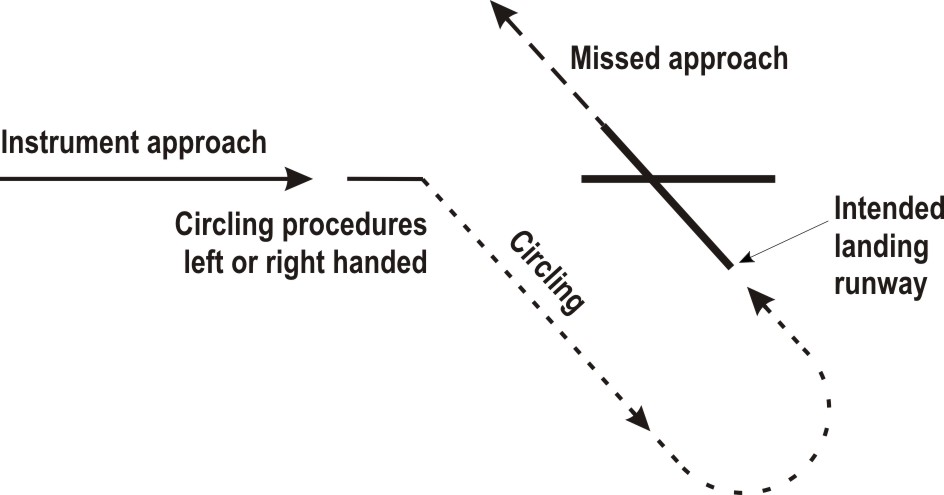
- If possible call Amsterdam ACC Supervisor on telephone number +31 (0)20 406 3999.
Note: use telephone connection to mitigate COM failure only. All telephone calls will be automatically recorded.
- If telephone connection is disconnected prematurely (before read-back), revert to general communication failure procedure.
For the general procedures for IFR flights see ENR 1.3 paragraph "Communication Failure". Additionally, for arriving flights, the following communication failure procedures apply.
Note: use telephone connection to mitigate COM failure only. All telephone calls will be automatically recorded.
- If telephone connection is disconnected prematurely (before read-back), revert to general communication failure procedure.
- Proceed according the current flight plan to the appropriate holding fix (ARTIP, RIVER and SUGOL).
- Maintain the last cleared and acknowledged flight level.
- After arrival over the fix, intercept the holding pattern.
- Commence descent to FL 070 at or as near as possible to the ETO over the holding fix.
- After reaching FL 070 leave the holding fix, proceed direct SPL VOR and carry out an instrument approach procedure to the received and acknowledged runway, or to the main landing runway according ATIS (see relevant instrument approach charts).
- Proceed according the current flight plan to the appropriate holding fix (ARTIP, RIVER and SUGOL).
- Maintain the last cleared and acknowledged flight level.
- After arrival over the fix, intercept the holding pattern.
- Commence descent to FL 070 at the EAT last received and acknowledged.
- When no EAT has been received and acknowledged, commence descent to FL 070 at or as near as possible to the ETO over the holding fix.
- After reaching FL 070 leave the holding fix, proceed direct SPL VOR and carry out an instrument approach procedure to the assigned landing runway, or to the main landing runway according ATIS (see relevant instrument approach charts).
- Proceed to NARSO.
- Maintain the last cleared and acknowledged flight level.
- After arrival over NARSO, intercept the holding pattern.
- Commence descent to FL 070 at the expected further clearance time (EFCT) last received and acknowledged.
- When no EFCT has been received and acknowledged, commence descent to FL 070 at or as near as possible to the ETO over NARSO.
- After reaching FL 070 leave NARSO and intercept SPL R-069 inbound to ARTIP.
- Without delay at ARTIP, proceed direct SPL VOR and carry out an instrument approach procedure to the assigned landing runway, or to the main landing runway according ATIS (see relevant instrument approach charts).
- Proceed to the SPL VOR along the route specified in the arrival clearance.
- Maintain the last cleared and acknowledged flight level.
- After arrival over the SPL VOR intercept the holding pattern to the received and acknowledged runway, or to the main landing runway according ATIS.
- In the holding descend to FL 070, if applicable.
- After reaching FL 070, leave the holding and carry out an instrument approach procedure to the assigned landing runway (see relevant instrument approach charts).
- With clearance for a transition, execute the cleared night transition and appropriate final approach procedure.
- Without clearance for a transition, and the last received and acknowledged runway is 06, 18C or 18R:
-
Without clearance for a transition, and the last received and acknowledged runway being any other runway:
- proceed to SPL VOR.
- maintain the last cleared and acknowledged flight level.
- after arrival over SPL VOR, intercept the holding pattern to the received and acknowledged runway.
- in the holding descend to FL 070, if applicable.
- after reaching FL 070, carry out an instrument approach procedure to the runway concerned (see relevant instrument approach charts).
Proceed in the most direct manner to the route specified in the arrival clearance and carry out one of the procedures as specified in paragraph 2.10.3.
See the relevant instrument approach charts.
Note:
This procedure is different from ICAO Doc 8168 Volume I (PANS-OPS).
|
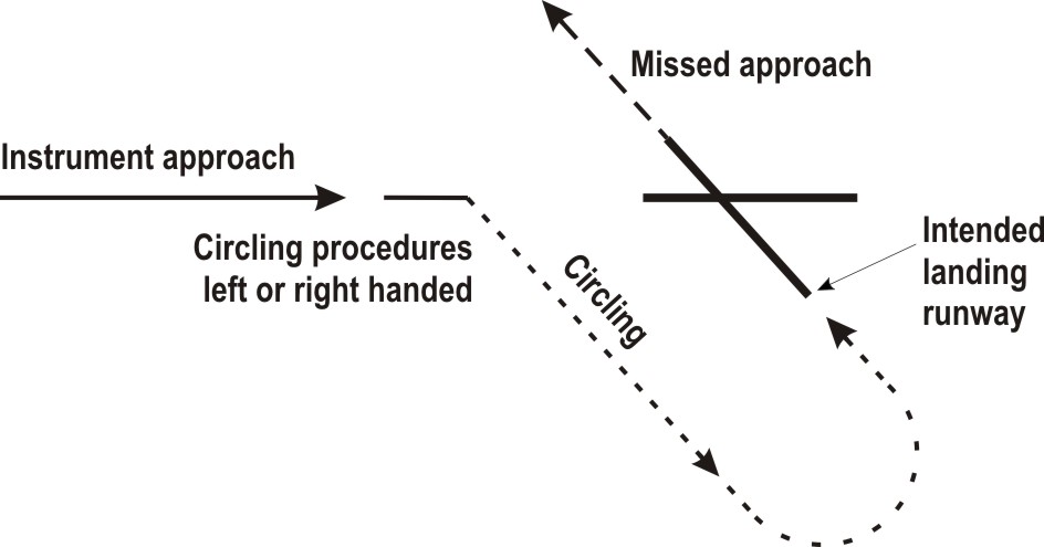
- Between IAFs and interception of final approach navigation is based on radar vectors provided by ATC, except in case of an RNAV procedure.
- ILS systems are not equipped with markers.
- Aircraft should monitor the emergency channel 121.500 to the extent possible. In case of failure on the regular channel ATC will use this emergency channel.
Between FIR entry and the IAFs, ATC may use the phrase "at pilot's discretion" in descent or speed instructions. In this case, the pilot is free to optimise the vertical and/or speed profile with the aim to fly a low noise continuous descent operation (CDO). ATC may provide vertical instructions that deviate from the charted altitudes on the STARs, intended to facilitate the CDO.
During night, using night transitions, some containing radius to fix (RF) segments, followed by an RNP final approach is preferred for noise abatement reasons. If unable, advise ATC and expect an ILS final approach. When RVR <= 1500 M and/or the cloud base <= 300 FT, an ILS final approach will be provided at ATC discretion.
The night transition procedures contain the lateral path, vertical- and speed profiles. When cleared for the transition fly the lateral path and adhere to altitude/level instructions by ATC. When cleared to "descend via" the applicable transition, execute a low noise CDO within the constraints as laid down in the procedure description. If unable to comply with the constraints, advise ATC.
Refer to EHAM AD 2.22 paragraph 2.7.2.2 for clearances and constraints.
Example: the ATC instruction "Descend via ARTIP 1A, cleared RNP approach RWY 06" is a clearance to fly the published night transition and RNP final approach to the relevant runway within the constraints of the procedure.
Note:
flights departing from Rotterdam or Lelystad inbound Schiphol are exempted from flying night transitions.
During night, using night transitions, some containing radius to fix (RF) segments, followed by an RNP final approach is preferred for noise abatement reasons. If unable, advise ATC and expect an ILS final approach. When RVR <= 1500 M and/or the cloud base <= 300 FT, an ILS final approach will be provided at ATC discretion.
The night transition procedures contain the lateral path, vertical- and speed profiles. When cleared for the transition fly the lateral path and adhere to altitude/level instructions by ATC. When cleared to "descend via" the applicable transition, execute a low noise CDO within the constraints as laid down in the procedure description. If unable to comply with the constraints, advise ATC.
Refer to EHAM AD 2.22 paragraph 2.7.2.2 for clearances and constraints.
Example: the ATC instruction "Descend via ARTIP 1A, cleared RNP approach RWY 06" is a clearance to fly the published night transition and RNP final approach to the relevant runway within the constraints of the procedure.
Navigation in the initial and intermediate approach segment is primarily based on radar vectors by ATC. For RWY 36R an RNAV transition providing a lateral path from ARTIP or INBAM to the FAP is available. The use of the RNAV transition is at ATC discretion.
Refer to EHAM AD 2.22 paragraph 2.7.2.3 for clearances and constraints.
For the ILS approach to RWY 36R a separate clearance will be issued.
Refer to EHAM AD 2.22 paragraph 2.7.2.3 for clearances and constraints.
For the ILS approach to RWY 36R a separate clearance will be issued.
Note:
recommended navaid for selection of MAG station declination only.
Note:
for positions of AM-waypoints see relevant instrument approach charts.
| Serial number |
Path
descriptor |
WPT ident | Fly-over |
Course/Track
°MAG / (°T) |
Recom.
navaid |
Dist. (NM) | Turn | Altitude (FT / FL) |
Speed
(KIAS) |
VPA (°) / TCH (FT) |
NAV
specification |
| 001 | IF | SPL | - | - | - | - | - | + FL 070 | - 220 | - | - |
| 002 | TF | AM201 | - | 174 /
(176.3) |
- | 10.3 | - | - | - | - | RNAV 1 |
| 003 | TF | AM202 | - | 219 /
(221.5) |
- | 4.2 | - | - | - | - | RNAV 1 |
| 004 | TF | AM203 | - | 309 /
(311.2) |
- | 3.4 | - | - | - | - | RNAV 1 |
| 005 | TF | NELFE | - | 349 /
(351.2) |
- | 2.2 | - | + 2000 | - 220 | - | RNAV 1 |
| 001 | IF | NELFE | - | - | - | - | - | + 2000 | - 220 | - | - |
| 002 | TF | AM204 | - | 039 /
(041.2) |
- | 3.2 | - | + 2000 | - | - | RNP APCH |
| 003 | TF | THR 04 | Y | 039 /
(041.2) |
- | 6.2 | - | - | - | -3.00 / 50 | RNP APCH |
| 004 | TF | AM205 | - | 039 /
(041.3) |
- | 13.1 | - | @ 2000 | - 220 | - | RNP APCH |
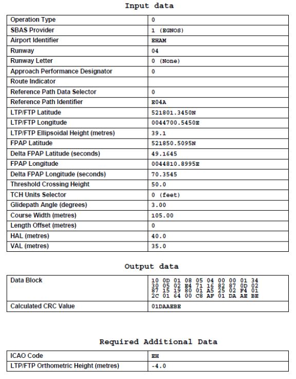
| Serial number |
Path
descriptor |
WPT ident | Fly-over |
Course/Track
°MAG / (°T) |
Recom.
navaid |
Dist. (NM) | Turn | Altitude (FT / FL) |
Speed
(KIAS) |
VPA (°) / TCH (FT) |
NAV
specification |
| 001 | IF | SPL | - | - | - | - | - | + FL 070 | - 220 | - | - |
| 002 | TF | AM101 | - | 281 /
(282.9) |
- | 4.2 | - | - | - | - | RNAV 1 |
| 003 | TF | AM102 | - | 235 /
(237.9) |
- | 9.6 | - | - | - | - | RNAV 1 |
| 004 | TF | AM103 | - | 145 /
(147.7) |
- | 3.2 | - | - | - | - | RNAV 1 |
| 005 | TF | OSRON | - | 105 /
(107.7) |
- | 2.2 | - | + 2000 | - 220 | - | RNAV 1 |
| 001 | IF | OSRON | - | - | - | - | - | + 2000 | - 220 | - | - |
| 002 | CF | AM110 | - | 055 /
(057.8) |
KAG | 1.7 | - | - | - | - | - |
| 003 | CF | AM609 | - | 055 /
(057.8) |
KAG | 1.5 | - | + 2000 | - | - | - |
| 004 | CF | THR 06 | Y | 055 /
(057.8) |
KAG | 6.2 | - | - | - | -3.00 / 50 | - |
| 005 | VA | - | - | 055 /
(057.8) |
- | - | - | @ 2000 | - 220 | - | - |
| Serial number |
Path
descriptor |
WPT ident | Fly-over |
Course/Track
°MAG / (°T) |
Recom.
navaid |
Dist. (NM) | Turn | Altitude (FT / FL) |
Speed
(KIAS) |
VPA (°) / TCH (FT) |
NAV
specification |
| 001 | IF | SPL | - | - | - | - | - | + FL 070 | - 220 | - | - |
| 002 | TF | AM101 | - | 281 /
(282.9) |
- | 4.2 | - | - | - | - | RNAV 1 |
| 003 | TF | AM102 | - | 235 /
(237.9) |
- | 9.6 | - | - | - | - | RNAV 1 |
| 004 | TF | AM103 | - | 145 /
(147.7) |
- | 3.2 | - | - | - | - | RNAV 1 |
| 005 | TF | OSRON | - | 105 /
(107.7) |
- | 2.2 | - | + 2000 | - 220 | - | RNAV 1 |
| 001 | IF | OSRON | - | - | - | - | - | + 2000 | - 220 | - | - |
| 002 | TF | AM609 | - | 055 /
(057.8) |
- | 3.2 | - | + 2000 | - | - | RNP APCH |
| 003 | TF | THR 06 | Y | 055 /
(057.8) |
- | 6.2 | - | - | - | -3.00 / 50 | RNP APCH |
| 004 | TF | AM104 | Y | 055 /
(057.9) |
- | 7.9 | - | - | - | - | RNP APCH |
| 005 | TF | AM105 | - | 056 /
(058.1) |
- | 4.5 | - | @ 2000 | - 220 | - | RNP APCH |
| Serial number |
Path
descriptor |
WPT ident | Fly-over |
Course/Track
°MAG / (°T) |
Recom.
navaid |
Dist. (NM) | Turn | Altitude (FT / FL) |
Speed
(KIAS) |
VPA (°) / TCH (FT) |
NAV
specification |
| 001 | IF | ARTIP | - | - | - | - | - | B FL 140 FL 100 | - | - | - |
| 002 | TF | PAM | - | 236 /
(239.0) |
- | 20.5 | - | - | - | - | RNAV 1 |
| 003 | TF | AM617 | - | 267 /
(269.4) |
- | 6.0 | - | + FL 100 | - 250 | - | RNAV 1 |
| 004 | TF | SETWO | - | 267 /
(269.3) |
- | 9.0 | - | + FL 070 | - | - | RNAV 1 |
| 005 | TF | AM612 | - | 267 /
(269.1) |
- | 11.3 | - | - | - | - | RNAV 1 |
| 006 | TF | SOKSI | - | 182 /
(184.4) |
- | 5.5 | - | + 4000 | - 220 | - | RNAV 1 |
| 007 | TF | AM613 | - | 113 /
(115.1) |
- | 4.0 | - | - | - | - | RNAV 1 |
| 008 | TF | AM614 | - | 089 /
(091.6) |
- | 2.4 | - | + 2900 | - | - | RNAV 1 |
| 009 | TF | AM110 | - | 055 /
(057.8) |
- | 1.5 | - | - | - | - | RNAV 1 |
| 010 | CF | AM609 | - | 055 /
(057.8) |
KAG | 1.5 | - | + 2000 | - | - | - |
| 011 | CF | THR 06 | Y | 055 /
(057.8) |
KAG | 6.2 | - | - | - | -3.00 / 50 | - |
| 012 | FM | THR 06 | - | 055 /
(057.8) |
KAG | - | - | @ 2000 | - | - | - |
| Serial number |
Path
descriptor |
WPT ident | Fly-over |
Course/Track
°MAG / (°T) |
Recom.
navaid |
Dist. (NM) | Turn | Altitude (FT / FL) |
Speed
(KIAS) |
VPA (°) / TCH (FT) |
NAV
specification |
| 001 | IF | RIVER | - | - | - | - | - | B FL 140 FL 100 | - | - | - |
| 002 | TF | PORWA | - | 354 /
(356.2) |
- | 9.2 | - | + FL 070 | - 250 | - | RNAV 1 |
| 003 | TF | AM610 | - | 023 /
(025.0) |
- | 9.2 | - | - | - | - | RNAV 1 |
| 004 | TF | SOKSI | - | 068 /
(069.9) |
- | 5.6 | - | + 4000 | - 220 | - | RNAV 1 |
| 005 | TF | AM613 | - | 113 /
(115.1) |
- | 4.0 | - | - | - | - | RNAV 1 |
| 006 | TF | AM614 | - | 089 /
(091.6) |
- | 2.4 | - | + 2900 | - | - | RNAV 1 |
| 007 | TF | AM110 | - | 055 /
(057.8) |
- | 1.5 | - | - | - | - | RNAV 1 |
| 008 | CF | AM609 | - | 055 /
(057.8) |
KAG | 1.5 | - | + 2000 | - | - | - |
| 009 | CF | THR 06 | Y | 055 /
(057.8) |
KAG | 6.2 | - | - | - | -3.00 / 50 | - |
| 010 | FM | THR 06 | - | 055 /
(057.8) |
KAG | - | - | @ 2000 | - | - | - |
| Serial number |
Path
descriptor |
WPT ident | Fly-over |
Course/Track
°MAG / (°T) |
Recom.
navaid |
Dist. (NM) | Turn | Altitude (FT / FL) |
Speed
(KIAS) |
VPA (°) / TCH (FT) |
NAV
specification |
| 001 | IF | SUGOL | - | - | - | - | - | B FL 140 FL 100 | - | - | - |
| 002 | TF | NETOM | - | 110 /
(111.7) |
- | 16.6 | - | - | - 250 | - | RNAV 1 |
| 003 | TF | SOKSI | - | 182 /
(184.5) |
- | 11.2 | - | + 4000 | - 220 | - | RNAV 1 |
| 004 | TF | AM613 | - | 113 /
(115.1) |
- | 4.0 | - | - | - | - | RNAV 1 |
| 005 | TF | AM614 | - | 089 /
(091.6) |
- | 2.4 | - | + 2900 | - | - | RNAV 1 |
| 006 | TF | AM110 | - | 055 /
(057.8) |
- | 1.5 | - | - | - | - | RNAV 1 |
| 007 | CF | AM609 | - | 055 /
(057.8) |
KAG | 1.5 | - | + 2000 | - | - | - |
| 008 | CF | THR 06 | Y | 055 /
(057.8) |
KAG | 6.2 | - | - | - | -3.00 / 50 | - |
| 009 | FM | THR 06 | - | 055 /
(057.8) |
KAG | - | - | @ 2000 | - | - | - |
| Serial number |
Path
descriptor |
WPT ident | Fly-over |
Course/Track
°MAG / (°T) |
Recom.
navaid |
Dist. (NM) | Turn | Altitude (FT / FL) |
Speed
(KIAS) |
VPA (°) / TCH (FT) |
NAV
specification |
| 001 | IF | ARTIP | - | - | - | - | - | B FL 140 FL 100 | - | - | - |
| 002 | TF | PAM | - |
(239.0) |
- | 20.5 | - | - | - | - | RNP APCH |
| 003 | TF | AM617 | - | 267 /
(269.4) |
- | 6.0 | - | +FL 100 | - 250 | - | RNP APCH |
| 004 | TF | SETWO | - | 267 /
(269.3) |
- | 9.0 | - | + FL 070 | - | - | RNP APCH |
| 005 | TF | AM612 | - | 267 /
(269.1) |
- | 11.3 | - | - | - | - | RNP APCH |
| 006 | TF | SOKSI | - | 182 /
(184.4) |
- | 5.5 | - | + 4000 | - 220 | - | RNP APCH |
| 007 | TF | AM613 | - | 113 /
(115.1) |
- | 4.0 | - | - | - | - | RNP APCH |
| 008 | TF | AM614 | - | 089 /
(091.6) |
- | 2.4 | - | + 2900 | - | - | RNP APCH |
| 009 | TF | AM110 | - | 055 /
(057.8) |
- | 1.5 | - | - | - | - | RNP APCH |
| 010 | TF | AM609 | - | 055 /
(057.8) |
- | 1.5 | - | + 2000 | - | - | RNP APCH |
| 011 | TF | THR 06 | Y | 055 /
(057.8) |
- | 6.2 | - | - | - | - 3.00 / 50 | RNP APCH |
| 012 | TF | AM104 | Y | 055 /
(057.9) |
- | 7.9 | - | - | - | - | RNP APCH |
| 013 | TF | AM105 | - | 056 /
(058.1) |
- | 4.5 | - | @ 2000 | - 220 | - | RNP APCH |
| Serial number |
Path
descriptor |
WPT ident | Fly-over |
Course/Track
°MAG / (°T) |
Recom.
navaid |
Dist. (NM) | Turn | Altitude (FT / FL) |
Speed
(KIAS) |
VPA (°) / TCH (FT) |
NAV
specification |
| 001 | IF | RIVER | - | - | - | - | - | B FL 140 FL 100 | - | - | - |
| 002 | TF | PORWA | - | 354 /
(356.2) |
- | 9.2 | - | + FL 070 | - 250 | - | RNP APCH |
| 003 | TF | AM610 | - | 023 /
(025.0) |
- | 9.2 | - | - | - | - | RNP APCH |
| 004 | TF | SOKSI | - | 068 /
(069.9) |
- | 5.6 | - | + 4000 | - 220 | - | RNP APCH |
| 005 | TF | AM613 | - | 113 /
(115.1) |
- | 4.0 | - | - | - | - | RNP APCH |
| 006 | TF | AM614 | - | 089 /
(091.6) |
- | 2.4 | - | + 2900 | - | - | RNP APCH |
| 007 | TF | AM110 | - | 055 /
(057.8) |
- | 1.5 | - | - | - | - | RNP APCH |
| 008 | TF | AM609 | - | 055 /
(057.8) |
- | 1.5 | - | + 2000 | - | - | RNP APCH |
| 009 | TF | THR 06 | Y | 055 /
(057.8) |
- | 6.2 | - | - | - | - 3.00 / 50 | RNP APCH |
| 010 | TF | AM104 | Y | 055 /
(057.9) |
- | 7.9 | - | - | - | - | RNP APCH |
| 011 | TF | AM105 | - | 056 /
(058.1) |
- | 4.5 | - | @ 2000 | - 220 | - | RNP APCH |
| Serial number |
Path
descriptor |
WPT ident | Fly-over |
Course/Track
°MAG / (°T) |
Recom.
navaid |
Dist. (NM) | Turn | Altitude (FT / FL) |
Speed
(KIAS) |
VPA (°) / TCH (FT) |
NAV
specification |
| 001 | IF | SUGOL | - | - | - | - | - | B FL 140 FL 100 | - | - | - |
| 002 | TF | NETOM | - | 110 /
(111.7) |
- | 16.6 | - | - | - 250 | - | RNP APCH |
| 003 | TF | SOKSI | - | 182 /
(184.4) |
- | 11.2 | - | + 4000 | - 220 | - | RNP APCH |
| 004 | TF | AM613 | - | 113 /
(115.1) |
- | 4.0 | - | - | - | - | RNP APCH |
| 005 | TF | AM614 | - | 089 /
(091.6) |
- | 2.4 | - | + 2900 | - | - | RNP APCH |
| 006 | TF | AM110 | - | 055 /
(057.8) |
- | 1.5 | - | - | - | - | RNP APCH |
| 007 | TF | AM609 | - | 055 /
(057.8) |
- | 1.5 | - | + 2000 | - | - | RNP APCH |
| 008 | TF | THR 06 | Y | 055 /
(057.8) |
- | 6.2 | - | - | - | - 3.00 / 50 | RNP APCH |
| 009 | TF | AM104 | Y | 055 /
(057.9) |
- | 7.9 | - | - | - | - | RNP APCH |
| 010 | TF | AM105 | - | 056 /
(058.1) |
- | 4.5 | - | @ 2000 | - 220 | - | RNP APCH |
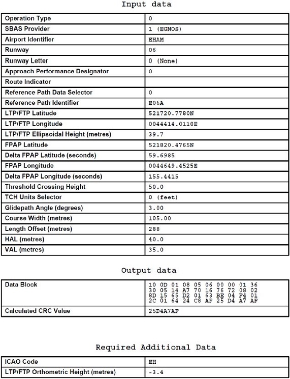
| Serial number |
Path
descriptor |
WPT ident | Fly-over |
Course/Track
°MAG / (°T) |
Recom.
navaid |
Dist. (NM) | Turn | Altitude (FT / FL) |
Speed
(KIAS) |
VPA (°) / TCH (FT) |
NAV
specification |
| 001 | IF | SPL | - | - | - | - | - | + FL 070 | - 220 | - | - |
| 002 | TF | AM220 | - | 309 /
(311.8) |
- | 5.8 | - | - | - | - | RNAV 1 |
| 003 | TF | AM221 | - | 264 /
(266.8) |
- | 6.8 | - | - | - | - | RNAV 1 |
| 004 | TF | AM222 | - | 174 /
(176.8) |
- | 3.3 | - | - | - | - | RNAV 1 |
| 005 | TF | IFTAZ | - | 134 /
(136.8) |
- | 2.3 | - | + 2000 | - 220 | - | RNAV 1 |
| 001 | IF | IFTAZ | - | - | - | - | - | + 2000 | - 220 | - | - |
| 002 | TF | AM223 | - | 084 /
(086.8) |
- | 3.2 | - | + 2000 | - | - | RNP APCH |
| 003 | TF | THR 09 | Y | 084 /
(086.8) |
- | 6.2 | - | - | - | -3.00 / 50 | RNP APCH |
| 004 | TF | AM224 | - | 084 /
(086.8) |
- | 13.1 | - | @ 2000 | - 220 | - | RNP APCH |
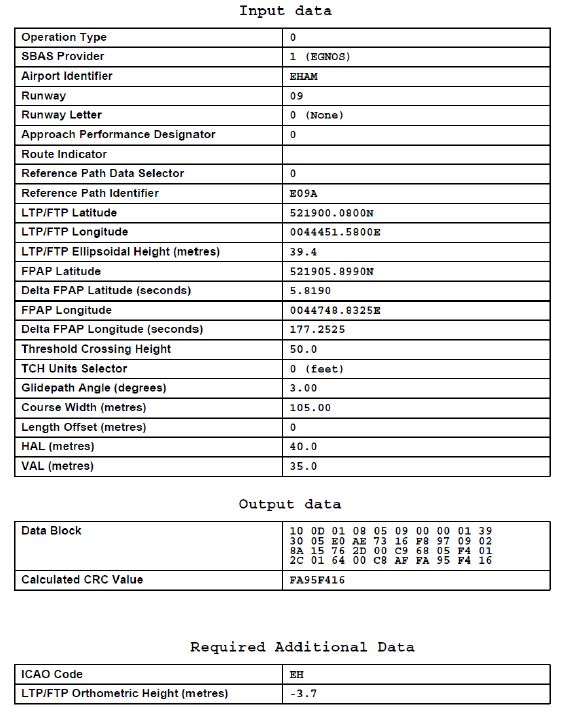
| Serial number |
Path
descriptor |
WPT ident | Fly-over |
Course/Track
°MAG / (°T) |
Recom.
navaid |
Dist. (NM) | Turn | Altitude (FT / FL) |
Speed
(KIAS) |
VPA (°) / TCH (FT) |
NAV
specification |
| 001 | IF | SPL | - | - | - | - | - | + FL 070 | - 220 | - | - |
| 002 | TF | AM120 | - | 046 /
(048.3) |
- | 6.5 | - | - | - | - | RNAV 1 |
| 003 | TF | AM121 | - | 001 /
(003.4) |
- | 6.2 | - | - | - | - | RNAV 1 |
| 004 | TF | AM122 | - | 271 /
(273.3) |
- | 3.2 | - | - | - | - | RNAV 1 |
| 005 | TF | SIDNI | - | 231 /
(233.3) |
- | 2.2 | - | + 3000 | - 220 | - | RNAV 1 |
| 001 | IF | ALINA | - | - | - | - | - | - | - 220 | - | - |
| 002 | CF | SIDNI | - | 181 /
(183.2) |
ZWA | 4.6 | - | + 3000 | - 220 | - | - |
| 001 | IF | SIDNI | - | - | - | - | - | + 3000 | - 220 | - | - |
| 002 | CF | AM630 | - | 181 /
(183.2) |
ZWA | 3.2 | - | + 2000 | - | - | - |
| 003 | CF | THR 18C | Y | 181 /
(183.2) |
ZWA | 6.2 | - | - | - | -3.00 / 50 | - |
| 004 | VA | - | - | 181 /
(183.2) |
- | - | - | @ 2000 | - 220 | - | - |
| Serial number |
Path
descriptor |
WPT ident | Fly-over |
Course/Track
°MAG / (°T) |
Recom.
navaid |
Dist. (NM) | Turn | Altitude (FT / FL) |
Speed
(KIAS) |
VPA (°) / TCH (FT) |
NAV
specification |
| 001 | IF | SPL | - | - | - | - | - | + FL 070 | - 220 | - | - |
| 002 | TF | AM120 | - | 046 /
(048.3) |
- | 6.5 | - | - | - | - | RNAV 1 |
| 003 | TF | AM121 | - | 001 /
(003.4) |
- | 6.2 | - | - | - | - | RNAV 1 |
| 004 | TF | AM122 | - | 271 /
(273.3) |
- | 3.2 | - | - | - | - | RNAV 1 |
| 005 | TF | SIDNI | - | 231 /
(233.3) |
- | 2.2 | - | + 2000 | - 220 | - | RNAV 1 |
| 001 | IF | ALINA | - | - | - | - | - | - | - 220 | - | - |
| 002 | TF | SIDNI | - | 181 /
(183.2) |
- | 4.6 | - | + 2000 | - 220 | - | RNAV 1 |
| 001 | IF | SIDNI | - | - | - | - | - | + 2000 | - 220 | - | - |
| 002 | TF | AM630 | - | 181/
(183.2) |
- | 3.2 | - | + 2000 | - | - | RNP APCH |
| 003 | TF | THR 18C | Y | 181 /
(183.2) |
- | 6.2 | - | - | - | -3.00 / 50 | RNP APCH |
| 004 | TF | AM123 | - | 181 /
(183.2) |
- | 13.2 | - | @ 2000 | - 220 | - | RNP APCH |
| Serial number |
Path
descriptor |
WPT ident | Fly-over |
Course/Track
°MAG / (°T) |
Recom.
navaid |
Dist. (NM) | Turn | Altitude (FT / FL) |
Speed
(KIAS) |
VPA (°) / TCH (FT) |
NAV
specification |
| 001 | IF | ARTIP | - | - | - | - | - | B FL 140 FL 100 | - | - | - |
| 002 | TF | WINJA | - | 290 /
(292.3) |
- | 28.4 | - | + FL 100 | - 250 | - | RNAV 1 |
| 003 | TF | AM602 | - | 268 /
(270.1) |
- | 6.2 | - | + FL 070 | - | - | RNAV 1 |
| 004 | TF | AM603 | - | 268 /
(270.0) |
- | 6.1 | L | - | - | - | RNAV 1 |
| 005 | TF | NIRSI | - | 178 /
(180.0) |
- | 6.3 | L | + FL 055 | - 220 | - | RNAV 1 |
| 006 | TF | AM607 | - | 088 /
(090.0) |
- | 4.9 | - | - | - | - | RNAV 1 |
| 007 | TF | AM608 | - | 130 /
(131.9) |
- | 4.0 | - | + 3400 | - | - | RNAV 1 |
| 008 | TF | SIDNI | - | 161 /
(163.0) |
- | 3.3 | - | - | - | - | RNAV 1 |
| 001 | IF | SIDNI | - | - | - | - | - | - | - | - | - |
| 002 | CF | AM630 | - | 181 /
(183.2) |
ZWA | 3.2 | - | + 2000 | - | - | - |
| 003 | CF | THR 18C | Y | 181 /
(183.2) |
ZWA | 6.2 | - | - | - | -3.00 / 50 | - |
| 004 | FM | THR 18C | - | 181 /
(183.2) |
ZWA | - | - | @ 2000 | - | - | - |
| Serial number |
Path
descriptor |
WPT ident | Fly-over |
Course/Track
°MAG / (°T) |
Recom.
navaid |
Dist. (NM) | Turn | Altitude (FT / FL) |
Speed
(KIAS) |
VPA (°) / TCH (FT) |
NAV
specification |
| 001 | IF | RIVER | - | - | - | - | - | B FL 140 FL 100 | - | - | - |
| 002 | TF | PORWA | - | 354 /
(356.2) |
- | 9.2 | - | - | - | - | RNAV 1 |
| 003 | TF | AM627 | - | 023 /
(025.0) |
- | 15.1 | - | + FL 100 | - 250 | - | RNAV 1 |
| 004 | TF | NETOM | - | 023 /
(025.1) |
- | 8.6 | - | + FL 070 | - | - | RNAV 1 |
| 005 | TF | NIRSI | - | 023 /
(025.3) |
- | 10.7 | - | + FL 055 | - 220 | - | RNAV 1 |
| 006 | TF | AM607 | - | 088 /
(090.0) |
- | 4.9 | - | - | - | - | RNAV 1 |
| 007 | TF | AM608 | - | 130 /
(131.9) |
- | 4.0 | - | + 3400 | - | - | RNAV 1 |
| 008 | TF | SIDNI | - | 161 /
(163.0) |
- | 3.3 | - | - | - | - | RNAV 1 |
| 001 | IF | SIDNI | - | - | - | - | - | - | - | - | - |
| 002 | CF | AM630 | - | 181 /
(183.2) |
ZWA | 3.2 | - | + 2000 | - | - | - |
| 003 | CF | THR 18C | Y | 181 /
(183.2) |
ZWA | 6.2 | - | - | - | -3.00 / 50 | - |
| 004 | FM | THR 18C | - | 181 /
(183.2) |
ZWA | - | - | @ 2000 | - | - | - |
| Serial number |
Path
descriptor |
WPT ident | Fly-over |
Course/Track
°MAG / (°T) |
Recom.
navaid |
Dist. (NM) | Turn | Altitude (FT / FL) |
Speed
(KIAS) |
VPA (°) / TCH (FT) |
NAV
specification |
| 001 | IF | SUGOL | - | - | - | - | - | B FL 140 FL 100 | - | - | - |
| 002 | TF | NETOM | - | 110 /
(111.7) |
- | 16.6 | - | + FL 070 | - 250 | - | RNAV 1 |
| 003 | TF | NIRSI | - | 023 /
(025.3) |
- | 10.7 | - | + FL 055 | - 220 | - | RNAV 1 |
| 004 | TF | AM607 | - | 088 /
(090.0) |
- | 4.9 | - | - | - | - | RNAV 1 |
| 005 | TF | AM608 | - | 130 /
(131.9) |
- | 4.0 | - | + 3400 | - | - | RNAV 1 |
| 006 | TF | SIDNI | - | 161 /
(163.0) |
- | 3.3 | - | - | - | - | RNAV 1 |
| 001 | IF | SIDNI | - | - | - | - | - | - | - | - | - |
| 002 | CF | AM630 | - | 181 /
(183.2) |
ZWA | 3.2 | - | + 2000 | - | - | - |
| 003 | CF | THR 18C | Y | 181 /
(183.2) |
ZWA | 6.2 | - | - | - | -3.00 / 50 | - |
| 004 | FM | THR 18C | - | 181 /
(183.2) |
ZWA | - | - | @ 2000 | - | - | - |
| Serial number |
Path
descriptor |
WPT ident | Fly-over |
Course/Track
°MAG / (°T) |
Recom.
navaid |
Dist. (NM) | Turn | Altitude (FT / FL) |
Speed
(KIAS) |
VPA (°) / TCH (FT) |
NAV
specification |
| 001 | IF | ARTIP | - | - | - | - | - | B FL 140 FL 100 | - | - | - |
| 002 | TF | WINJA | - | 290 /
(292.3) |
- | 28.4 | - | + FL 100 | - 250 | - | RNP APCH |
| 003 | TF | AM602 | - | 268 /
(270.1) |
- | 6.2 | - | + FL 070 | - | - | RNP APCH |
| 004 | TF | AM603 | - | 268 /
(270.0) |
- | 6.1 | L | - | - | - | RNP APCH |
| 005 | TF | NIRSI | - | 178 /
(180.0) |
- | 6.3 | L | + FL 055 | - 220 | - | RNP APCH |
| 006 | TF | AM607 | - | 088 /
(090.0) |
- | 4.9 | - | - | - | - | RNP APCH |
| 007 | TF | AM126 | - | 125 /
(127.3) |
- | 2.8 | - | + 3400 | - | - | RNP APCH |
| 008 | RF centre:
AM127 r=2.50 NM |
AM128 | - | - | - | 3.3 | R | - | - | - | RNP APCH |
| 009 | RF centre:
AM129 r=2.67 NM |
AM130 | - | - | - | 2.7 | L | - | - | - | RNP APCH |
| 010 | RF centre:
AM131 r=2.77 NM |
AM630 | - | - | - | 1.8 | R | + 2000 | - | - | RNP APCH |
| 001 | IF | AM630 | - | - | - | - | - | + 2000 | - | - | - |
| 002 | TF | THR 18C | Y | 181 /
(183.2) |
- | 6.2 | - | - | - | -3.00 / 50 | RNP APCH |
| 003 | TF | AM123 | - | 181 /
(183.2) |
- | 13.2 | - | @ 2000 | - | - | RNP APCH |
| Serial number |
Path
descriptor |
WPT ident | Fly-over |
Course/Track
°MAG / (°T) |
Recom.
navaid |
Dist. (NM) | Turn | Altitude (FT / FL) |
Speed
(KIAS) |
VPA (°) / TCH (FT) |
NAV
specification |
| 001 | IF | RIVER | - | - | - | - | - | B FL 140 FL 100 | - | - | - |
| 002 | TF | PORWA | - | 354 /
(356.2) |
- | 9.2 | - | - | - | - | RNP APCH |
| 003 | TF | AM627 | - | 023 /
(025.0) |
- | 15.1 | - | + FL 100 | - 250 | - | RNP APCH |
| 004 | TF | NETOM | - | 023 /
(025.1) |
- | 8.6 | - | + FL 070 | - | - | RNP APCH |
| 005 | TF | NIRSI | - | 023 /
(025.3) |
- | 10.7 | - | + FL 055 | - 220 | - | RNP APCH |
| 006 | TF | AM607 | - | 088 /
(090.0) |
- | 4.9 | - | - | - | - | RNP APCH |
| 007 | TF | AM126 | - | 125 /
(127.3) |
- | 2.8 | - | + 3400 | - | - | RNP APCH |
| 008 | RF centre:
AM127 r=2.50 NM |
AM128 | - | - | - | 3.3 | R | - | - | - | RNP APCH |
| 009 | RF centre:
AM129 r=2.67 NM |
AM130 | - | - | - | 2.7 | L | - | - | - | RNP APCH |
| 010 | RF centre:
AM131 r=2.77 NM |
AM630 | - | - | - | 1.8 | R | + 2000 | - | - | RNP APCH |
| 001 | IF | AM630 | - | - | - | - | - | + 2000 | - | - | - |
| 002 | TF | THR 18C | Y | 181 /
(183.2) |
- | 6.2 | - | - | - | -3.00 / 50 | RNP APCH |
| 003 | TF | AM123 | - | 181 /
(183.2) |
- | 13.2 | - | @ 2000 | - | - | RNP APCH |
| Serial number |
Path
descriptor |
WPT ident | Fly-over |
Course/Track
°MAG / (°T) |
Recom.
navaid |
Dist. (NM) | Turn | Altitude (FT / FL) |
Speed
(KIAS) |
VPA (°) / TCH (FT) |
NAV
specification |
| 001 | IF | SUGOL | - | - | - | - | - | B FL 140 FL 100 | - | - | - |
| 002 | TF | NETOM | - | 110 /
(111.7) |
- | 16.6 | - | + FL 070 | - 250 | - | RNP APCH |
| 003 | TF | NIRSI | - | 023 /
(025.3) |
- | 10.7 | - | + FL 055 | - 220 | - | RNP APCH |
| 004 | TF | AM607 | - | 088 /
(090.0) |
- | 4.9 | - | - | - | - | RNP APCH |
| 005 | TF | AM126 | - | 125 /
(127.3) |
- | 2.8 | - | + 3400 | - | - | RNP APCH |
| 006 | RF centre:
AM127 r=2.50 NM |
AM128 | - | - | - | 3.3 | R | - | - | - | RNP APCH |
| 007 | RF centre:
AM129 r=2.67 NM |
AM130 | - | - | - | 2.7 | L | - | - | - | RNP APCH |
| 008 | RF centre:
AM131 r=2.77 NM |
AM630 | - | - | - | 1.8 | R | + 2000 | - | - | RNP APCH |
| 001 | IF | AM630 | - | - | - | - | - | + 2000 | - | - | - |
| 002 | TF | THR 18C | Y | 181 /
(183.2) |
- | 6.2 | - | - | - | -3.00 / 50 | RNP APCH |
| 003 | TF | AM123 | - | 181 /
(183.2) |
- | 13.2 | - | @ 2000 | - | - | RNP APCH |
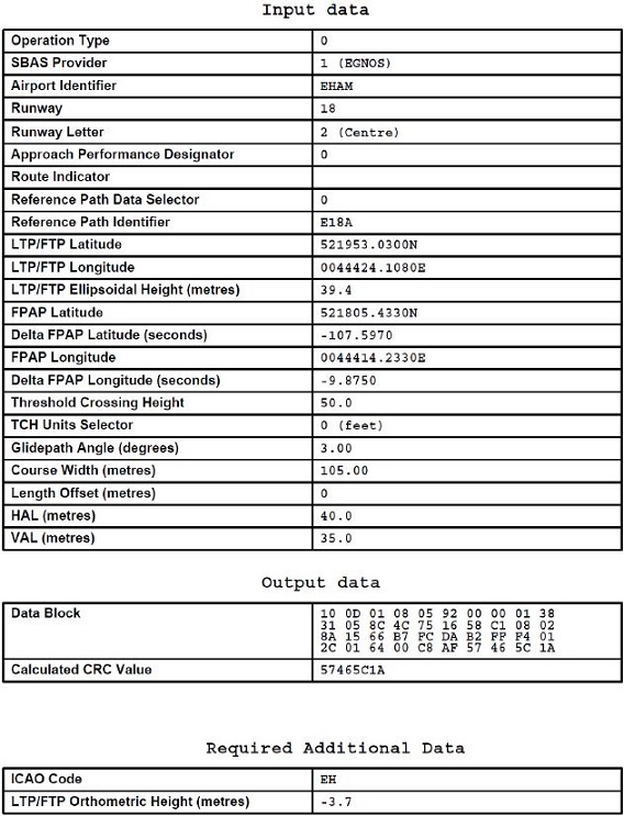
| Serial number |
Path
descriptor |
WPT ident | Fly-over |
Course/Track
°MAG / (°T) |
Recom.
navaid |
Dist. (NM) | Turn | Altitude (FT / FL) |
Speed
(KIAS) |
VPA (°) / TCH (FT) |
NAV
specification |
| 001 | IF | SPL | - | - | - | - | - | + FL 070 | - 220 | - | - |
| 002 | TF | AM240 | - | 316 /
(318.2) |
- | 9.1 | - | - | - | - | RNAV 1 |
| 003 | TF | AM241 | - | 001 /
(003.1) |
- | 6.0 | - | - | - | - | RNAV 1 |
| 004 | TF | AM242 | - | 091 /
(093.1) |
- | 3.2 | - | - | - | - | RNAV 1 |
| 005 | TF | PEVOS | - | 131 /
(133.1) |
- | 2.2 | - | + 2000 | - 220 | - | RNAV 1 |
| 001 | IF | DIBRU | - | - | - | - | - | - | - 220 | - | - |
| 002 | CF | PEVOS | - | 181 /
(183.2) |
VPB | 3.6 | - | + 2000 | - 220 | - | - |
| 001 | IF | PEVOS | - | - | - | - | - | + 2000 | - 220 | - | - |
| 002 | CF | AM621 | - | 181 /
(183.2) |
VPB | 3.2 | - | + 2000 | - | - | - |
| 003 | CF | THR 18R | - | 181 /
(183.2) |
VPB | 6.2 | - | - | - | -3.00 / 50 | - |
| 004 | FA | THR 18R | - | 181 /
(183.2) |
VPB | - | - | + 500 | - | - | RNAV 1 |
| 005 | DF | AM624 | - | - | - | - | R | @ 2000 | - 220 | - | RNAV 1 |
| 006 | FM | AM624 | - | 299 /
(301.3) |
VPB | - | - | @ 2000 | - | - | RNAV 1 |
| Serial number |
descriptor |
|
Fly-over |
Course/Track
°MAG / (°T) |
Recom.
navaid |
Dist. (NM) | Turn | Altitude (FT / FL) |
Speed
(KIAS) |
VPA (°) / TCH (FT) | NAV specification |
| 001 | IF | SPL | - | - | - | - | - | + FL 070 | - 220 | - | - |
| 002 | TF | AM240 | - | 316 / (318.2) | - | 9.1 | - | - | - | - | RNAV 1 |
| 003 | TF | AM241 | - | 001 / (003.1) | - | 6.0 | - | - | - | - | RNAV 1 |
| 004 | TF | AM242 | - | 091 / (093.1) | - | 3.2 | - | - | - | - | RNAV 1 |
| 005 | TF | PEVOS | - | 131 / (133.1) | - | 2.2 | - | + 2000 | - 220 | - | RNAV 1 |
| 001 | IF | DIBRU | - | - | - | - | - | - | - 220 | - | - |
| 002 | TF | PEVOS | - | 181 / (183.2) | - | 3.6 | - | + 2000 | - 220 | - | RNAV 1 |
| 001 | IF | PEVOS | - | - | - | - | - | + 2000 | - 220 | - | - |
| 002 | TF | AM621 | - | 181 / (183.2) | - | 3.2 | - | + 2000 | - | - | RNP APCH |
| 003 | TF | THR 18R | Y | 181 / (183.2) | - | 6.2 | - | - | - | -3.00 / 50 | RNP APCH |
| 004 | FA | THR 18R | - | 181 / (183.2) | SPL | - | - | + 500 | - | - | RNP APCH |
| 005 | DF | AM624 | - | - | - | - | R | @ 2000 | - 220 | - | RNP APCH |
| 006 | FM | AM624 | - | 299 / (301.3) | SPL | - | - | @ 2000 | - | - | RNP APCH |
| Serial number |
Path
descriptor |
WPT ident | Fly-over |
Course/Track
°MAG / (°T) |
Recom.
navaid |
Dist. (NM) | Turn | Altitude (FT / FL) |
Speed
(KIAS) |
VPA (°) / TCH (FT) |
NAV
specification |
| 001 | IF | ARTIP | - | - | - | - | - | B FL 140 FL 100 | - | - | - |
| 002 | TF | WINJA | - | 290 /
(292.3) |
- | 28.4 | - | + FL 100 | - 250 | - | RNAV 1 |
| 003 | TF | AM602 | - | 268 /
(270.1) |
- | 6.2 | - | + FL 070 | - | - | RNAV 1 |
| 004 | TF | AM603 | - | 268 /
(270.0) |
- | 6.1 | L | - | - | - | RNAV 1 |
| 005 | TF | NIRSI | - | 178 /
(180.0) |
- | 6.3 | L | + FL 055 | - 220 | - | RNAV 1 |
| 006 | TF | AM607 | - | 088 /
(089.9) |
- | 4.9 | - | - | - | - | RNAV 1 |
| 007 | TF | AM608 | - | 129 /
(131.9) |
- | 4.0 | - | + 3400 | - | - | RNAV 1 |
| 008 | CF | AM621 | - | 181 /
(183.2) |
VPB | 4.6 | - | + 2000 | - | - | - |
| 009 | CF | THR 18R | - | 181 /
(183.2) |
VPB | 6.2 | - | - | - | -3.00 / 50 | - |
| 010 | FA | THR 18R | - | 181 /
(183.2) |
VPB | - | - | + 500 | - | - | RNAV 1 |
| 011 | DF | AM624 | - | - | - | - | R | @ 2000 | - 220 | - | RNAV 1 |
| 012 | FM | AM624 | - | 299 /
(301.3) |
VPB | - | - | @ 2000 | - | - | RNAV 1 |
| Serial number |
Path
descriptor |
WPT ident | Fly-over |
Course/Track
°MAG / (°T) |
Recom.
navaid |
Dist. (NM) | Turn | Altitude (FT / FL) |
Speed
(KIAS) |
VPA (°) / TCH (FT) |
NAV
specification |
| 001 | IF | RIVER | - | - | - | - | - | B FL 140 FL 100 | - | - | - |
| 002 | TF | PORWA | - | 354 /
(356.2) |
- | 9.2 | - | - | - | - | RNAV 1 |
| 003 | TF | AM627 | - | 023 /
(025.0) |
- | 15.1 | - | + FL 100 | - 250 | - | RNAV 1 |
| 004 | TF | NETOM | - | 023 /
(025.1) |
- | 8.6 | - | + FL 070 | - | - | RNAV 1 |
| 005 | TF | NIRSI | - | 023 /
(025.3) |
- | 10.7 | - | + FL 055 | - 220 | - | RNAV 1 |
| 006 | TF | AM607 | - | 088 /
(089.9) |
- | 4.9 | - | - | - | - | RNAV 1 |
| 007 | TF | AM608 | - | 129 /
(131.9) |
- | 4.0 | - | + 3400 | - | - | RNAV 1 |
| 008 | CF | AM621 | - | 181 /
(183.2) |
VPB | 4.6 | - | + 2000 | - | - | - |
| 009 | CF | THR 18R | - | 181 /
(183.2) |
VPB | 6.2 | - | - | - | -3.00 / 50 | - |
| 010 | FA | THR 18R | - | 181 /
(183.2) |
VPB | - | - | + 500 | - | - | RNAV 1 |
| 011 | DF | AM624 | - | - | - | - | R | @ 2000 | - 220 | - | RNAV 1 |
| 012 | FM | AM624 | - | 299 /
(301.3) |
VPB | - | - | @ 2000 | - | - | RNAV 1 |
| Serial number |
Path
descriptor |
WPT ident | Fly-over |
Course/Track
°MAG / (°T) |
Recom.
navaid |
Dist. (NM) | Turn | Altitude (FT / FL) |
Speed
(KIAS) |
VPA (°) / TCH (FT) |
NAV
specification |
| 001 | IF | SUGOL | - | - | - | - | - | B FL 140 FL 100 | - | - | - |
| 002 | TF | NETOM | - | 110 /
(111.7) |
- | 16.6 | - | + FL 070 | - 250 | - | RNAV 1 |
| 003 | TF | NIRSI | - | 023 /
(025.3) |
- | 10.7 | - | + FL 055 | - 220 | - | RNAV 1 |
| 004 | TF | AM607 | - | 088 /
(089.9) |
- | 4.9 | - | - | - | - | RNAV 1 |
| 005 | TF | AM608 | - | 129 /
(131.9) |
- | 4.0 | - | + 3400 | - | - | RNAV 1 |
| 006 | CF | AM621 | - | 181 /
(183.2) |
VPB | 4.6 | - | + 2000 | - | - | - |
| 007 | CF | THR 18R | - | 181 /
(183.2) |
VPB | 6.2 | - | - | - | -3.00 / 50 | - |
| 008 | FA | THR 18R | - | 181 /
(183.2) |
VPB | - | - | + 500 | - | - | RNAV 1 |
| 009 | DF | AM624 | - | - | - | - | R | @ 2000 | - 220 | - | RNAV 1 |
| 010 | FM | AM624 | - | 299 /
(301.3) |
VPB | - | - | @ 2000 | - | - | RNAV 1 |
| Serial number |
Path
descriptor |
WPT ident | Fly-over |
Course/Track
°MAG / (°T) |
Recom.
navaid |
Dist. (NM) | Turn | Altitude (FT / FL) |
Speed
(KIAS) |
VPA (°) / TCH (FT) |
NAV
specification |
| 001 | IF | ARTIP | - | - | - | - | - | B FL 140 FL 100 | - | - | - |
| 002 | TF | WINJA | - | 290 /
(292.3) |
- | 28.4 | - | + FL 100 | - 250 | - | RNP APCH |
| 003 | TF | AM602 | - | 268 /
(270.1) |
- | 6.2 | - | + FL 070 | - | - | RNP APCH |
| 004 | TF | AM603 | - | 268 /
(270.0) |
- | 6.1 | L | - | - | - | RNP APCH |
| 005 | TF | NIRSI | - | 178 /
(180.0) |
- | 6.3 | L | + FL 055 | - 220 | - | RNP APCH |
| 006 | TF | AM607 | - | 088 /
(089.9) |
- | 4.9 | - | - | - | - | RNP APCH |
| 007 | TF | AM133 | - | 129 /
(131.9) |
- | 3.2 | - | + 3400 | - | - | RNP APCH |
| 008 | RF centre:
AM134 r=2.50 NM |
AM135 | - | - | - | 3.1 | R | - | - | - | RNP APCH |
| 009 | RF centre:
AM136 r=2.50 NM |
AM137 | - | - | - | 0.9 | L | - | - | - | RNP APCH |
| 010 | TF | AM621 | - | 181 /
(183.1) |
- | 1.4 | - | + 2000 | - | - | RNP APCH |
| 001 | IF | AM621 | - | - | - | - | - | + 2000 | - | - | - |
| 002 | TF | THR 18R | Y | 181 /
(183.2) |
- | 6.2 | - | - | - | -3.00 / 50 | RNP APCH |
| 003 | FA | THR 18R | - | 181 /
(183.2) |
SPL | - | - | + 500 | - | - | RNP APCH |
| 004 | DF | AM624 | - | - | - | - | R | @ 2000 | - 220 | - | RNP APCH |
| 005 | FM | AM624 | - | 299 /
(301.3) |
SPL | - | - | @ 2000 | - | - | RNP APCH |
| Serial number |
Path
descriptor |
WPT ident | Fly-over |
Course/Track
°MAG / (°T) |
Recom.
navaid |
Dist. (NM) | Turn | Altitude (FT / FL) |
Speed
(KIAS) |
VPA (°) / TCH (FT) |
NAV
specification |
| 001 | IF | RIVER | - | - | - | - | - | B FL 140 FL 100 | - | - | - |
| 002 | TF | PORWA | - | 354 /
(356.2) |
- | 9.2 | - | - | - | - | RNP APCH |
| 003 | TF | AM627 | - | 023 /
(025.0) |
- | 15.1 | - | + FL 100 | - 250 | - | RNP APCH |
| 004 | TF | NETOM | - | 023 /
(025.1) |
- | 8.6 | - | + FL 070 | - | - | RNP APCH |
| 005 | TF | NIRSI | - | 023 /
(025.3) |
- | 10.7 | - | + FL 055 | - 220 | - | RNP APCH |
| 006 | TF | AM607 | - | 088 /
(089.9) |
- | 4.9 | - | - | - | - | RNP APCH |
| 007 | TF | AM133 | - | 129 /
(131.9) |
- | 3.2 | - | + 3400 | - | - | RNP APCH |
| 008 | RF centre:
AM134 r=2.50 NM |
AM135 | - | - | - | 3.1 | R | - | - | - | RNP APCH |
| 009 | RF centre:
AM136 r=2.50 NM |
AM137 | - | - | - | 0.9 | L | - | - | - | RNP APCH |
| 010 | TF | AM621 | - | 181 /
(183.1) |
- | 1.4 | - | + 2000 | - | - | RNP APCH |
| 001 | IF | AM621 | - | - | - | - | - | + 2000 | - | - | - |
| 002 | TF | THR 18R | Y | 181 /
(183.2) |
- | 6.2 | - | - | - | -3.00 / 50 | RNP APCH |
| 003 | FA | THR 18R | - | 181 /
(183.2) |
SPL | - | - | + 500 | - | - | RNP APCH |
| 004 | DF | AM624 | - | - | - | - | R | @ 2000 | - 220 | - | RNP APCH |
| 005 | FM | AM624 | - | 299 /
(301.3) |
SPL | - | - | @ 2000 | - | - | RNP APCH |
| Serial number |
Path
descriptor |
WPT ident | Fly-over |
Course/Track
°MAG / (°T) |
Recom.
navaid |
Dist. (NM) | Turn | Altitude (FT / FL) |
Speed
(KIAS) |
VPA (°) / TCH (FT) |
NAV
specification |
| 001 | IF | SUGOL | - | - | - | - | - | B FL 140 FL 100 | - | - | - |
| 002 | TF | NETOM | - | 110 /
(111.7) |
- | 16.6 | - | + FL 070 | - 250 | - | RNP APCH |
| 003 | TF | NIRSI | - | 023 /
(025.3) |
- | 10.7 | - | + FL 055 | - 220 | - | RNP APCH |
| 004 | TF | AM607 | - | 088 /
(089.9) |
- | 4.9 | - | - | - | - | RNP APCH |
| 005 | TF | AM133 | - | 129 /
(131.9) |
- | 3.2 | - | + 3400 | - | - | RNP APCH |
| 006 | RF centre:
AM134 r=2.50 NM |
AM135 | - | - | - | 3.1 | R | - | - | - | RNP APCH |
| 007 | RF centre:
AM136 r=2.50 NM |
AM137 | - | - | - | 0.9 | L | - | - | - | RNP APCH |
| 008 | TF | AM621 | - | 181 /
(183.1) |
- | 1.4 | - | + 2000 | - | - | RNP APCH |
| 001 | IF | AM621 | - | - | - | - | - | + 2000 | - | - | - |
| 002 | TF | THR 18R | Y | 181 /
(183.2) |
- | 6.2 | - | - | - | -3.00 / 50 | RNP APCH |
| 003 | FA | THR 18R | - | 181 /
(183.2) |
SPL | - | - | + 500 | - | - | RNP APCH |
| 004 | DF | AM624 | - | - | - | - | R | @ 2000 | - 220 | - | RNP APCH |
| 005 | FM | AM624 | - | 299 /
(301.3) |
SPL | - | - | @ 2000 | - | - | RNP APCH |
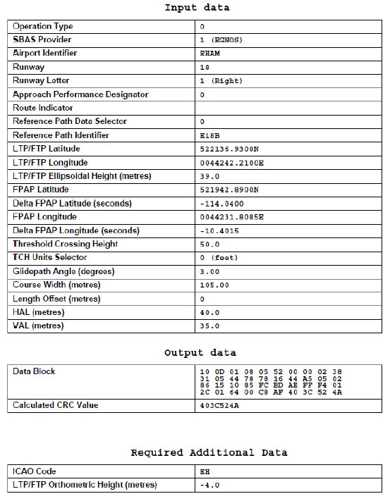
| Serial number |
Path
descriptor |
WPT ident | Fly-over |
Course/Track
°MAG / (°T) |
Recom.
navaid |
Dist. (NM) | Turn | Altitude (FT / FL) |
Speed
(KIAS) |
VPA (°) / TCH (FT) |
NAV
specification |
| 001 | IF | SPL | - | - | - | - | - | + FL 070 | - 220 | - | - |
| 002 | TF | PAM | - | 087 /
(089.2) |
- | 12.6 | - | - | - | - | RNAV 1 |
| 003 | TF | AM180 | - | 021 /
(023.8) |
- | 7.1 | - | - | - | - | RNAV 1 |
| 004 | TF | AM181 | - | 315 /
(317.4) |
- | 3.4 | - | - | - | - | RNAV 1 |
| 005 | TF | AM649 | - | 250 /
(253.0) |
- | 3.2 | - | + 3000 | - 220 | - | RNAV 1 |
| 001 | IF | AM649 | - | - | - | - | - | + 3000 | - 220 | - | - |
| 002 | CF | AM650 | - | 219 /
(221.3) |
- | 3.0 | - | + 3000 | - | - | - |
| 003 | CF | AM651 | - | 219 /
(221.3) |
SCH | 5.3 | - | - | - | -3.00 / - | - |
| 004 | CF | AM652 | Y | 219 /
(221.3) |
SCH | 2.8 | - | - | - | -3.00 / 46 | - |
| 005 | VA | - | - | 219 /
(221.3) |
- | - | - | + 400 | - | - | - |
| 006 | VA | - | - | 158 /
(160.4) |
- | - | - | @ 2000 | - | - | - |
| Serial number |
Path
descriptor |
WPT ident | Fly-over |
Course/Track
°MAG / (°T) |
Recom.
navaid |
Dist. (NM) | Turn | Altitude (FT / FL) |
Speed
(KIAS) |
VPA (°) / TCH (FT) |
NAV
specification |
| 001 | IF | HDR | - | - | - | - | - | @ 2000 | - | - | RNAV 1 |
| 002 | TF | NIDOP | - | 152 /
(154.1) |
- | 9.9 | - | @ 2000 | - | - | RNAV 1 |
| 003 | TF | AM409 | - | 152 /
(154.1) |
- | 11.2 | - | @ 2000 | - | - | RNAV 1 |
| 004 | CF | AM410 | - | 175 /
(178.0) |
SCH | 7.4 | - | @ 2000 | - | - | RNAV 1 |
| 001 | IF | AM410 | - | - | - | - | - | @ 2000 | - | - | - |
| 002 | CF | AM661 | - | 219 /
(221.3) |
SCH | 6.2 | - | @ 2000 | - | - | - |
| 003 | CF | AM651 | - | 219 /
(221.3) |
SCH | 2.2 | - | - | - | -3.00 / - | - |
| 004 | CF | AM652 | Y | 219 /
(221.3) |
SCH | 2.8 | - | - | - | -3.00 / 46 | - |
| 005 | VA | - | - | 219 /
(221.3) |
- | - | - | + 400 | - | - | - |
| 006 | VA | - | - | 158 /
(160.4) |
- | - | - | @ 2000 | - | - | - |
| Serial number |
Path
descriptor |
WPT ident | Fly-over |
Course/Track
°MAG / (°T) |
Recom.
navaid |
Dist. (NM) | Turn | Altitude (FT / FL) |
Speed
(KIAS) |
VPA (°) / TCH (FT) |
NAV
specification |
| 001 | IF | SPL | - | - | - | - | - | + FL 070 | - 220 | - | - |
| 002 | TF | PAM | - | 087 /
(089.2) |
- | 12.6 | - | - | - | - | RNAV 1 |
| 003 | TF | AMEGA | - | 002 /
(004.4) |
- | 4.6 | - | + 3000 | - 220 | - | RNAV 1 |
| 004 | TF | AM672 | - | 298 /
(300.0) |
- | 3.2 | - | - | - 190 | - | RNAV 1 |
| 005 | TF | BLUSY | - | 264 /
(266.4) |
- | 1.8 | - | + 2000 | - 190 | - | RNAV 1 |
| 006 | IF | AGOGO | - | - | - | - | - | + 3000 | - 220 | - | - |
| 007 | TF | AM671 | - | 124 /
(126.4) |
- | 3.2 | - | - | - 190 | - | RNAV 1 |
| 008 | TF | BLUSY | - | 174 /
(176.4) |
- | 1.8 | - | + 2000 | - 190 | - | RNAV 1 |
| 009 | IF | BLUSY | - | - | - | - | - | + 2000 | - 190 | - | - |
| 010 | TF | AM661 | - | 219 /
(221.4) |
- | 3.5 | - | + 2000 | - 185 | - | RNP APCH |
| 011 | TF | THR22 | Y | 219 /
(221.4) |
- | 6.2 | - | - | - | -3.00 / 50 | RNP APCH |
| 012 | CA | - | - | 219 /
(221.3) |
- | - | - | + 400 | - | - | RNP APCH |
| 013 | DF | AM675 | - | - | - | - | L | @ 2000 | - 220 | - | RNP APCH |
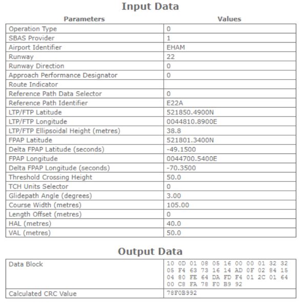
| Serial number |
Path
descriptor |
WPT ident | Fly-over |
Course/Track
°MAG / (°T) |
Recom.
navaid |
Dist. (NM) | Turn | Altitude (FT / FL) |
Speed
(KIAS) |
VPA (°) / TCH (FT) |
NAV
specification |
| 001 | IF | SPL | - | - | - | - | - | + FL 070 | - 220 | - | - |
| 002 | TF | AM140 | - | 011 /
(013.0) |
- | 4.3 | - | - | - | - | RNAV 1 |
| 003 | TF | AM141 | - | 056 /
(058.0) |
- | 7.7 | - | - | - | - | RNAV 1 |
| 004 | TF | AM142 | - | 146 /
(148.1) |
- | 3.2 | - | - | - | - | RNAV 1 |
| 005 | TF | ARWIN | - | 186 /
(188.1) |
- | 2.2 | - | + 2000 | - 220 | - | RNAV 1 |
| 001 | IF | ARWIN | - | - | - | - | - | + 2000 | - 220 | - | - |
| 002 | TF | AM143 | - | 236 /
(238.1) |
- | 3.2 | - | + 2000 | - | - | RNP APCH |
| 003 | TF | THR 24 | Y | 236 /
(238.1) |
- | 6.2 | - | - | - | -3.00 / 50 | RNP APCH |
| 004 | TF | AM144 | - | 236 /
(238.0) |
- | 13.0 | - | @ 2000 | - 220 | - | RNP APCH |
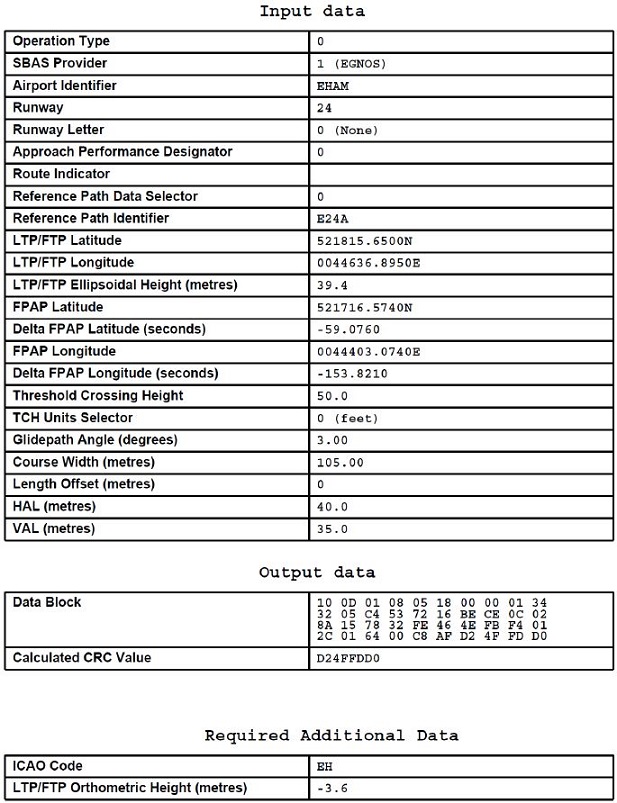
| Serial number |
Path
descriptor |
WPT ident | Fly-over |
Course/Track
°MAG / (°T) |
Recom.
navaid |
Dist. (NM) | Turn | Altitude (FT / FL) |
Speed
(KIAS) |
VPA (°) / TCH (FT) |
NAV
specification |
| 001 | IF | SPL | - | - | - | - | - | + FL 070 | - 220 | - | - |
| 002 | TF | AM260 | - | 039 /
(040.9) |
- | 5.7 | - | - | - | - | RNAV 1 |
| 003 | TF | AM261 | - | 084 /
(086.9) |
- | 8.5 | - | - | - | - | RNAV 1 |
| 004 | TF | AM262 | - | 175 /
(177.0) |
- | 3.2 | - | - | - | - | RNAV 1 |
| 005 | TF | TIDVO | - | 215 /
(217.1) |
- | 2.2 | - | + 2000 | - 220 | - | RNAV 1 |
| 001 | IF | TIDVO | - | - | - | - | - | + 2000 | - 220 | - | - |
| 002 | CF | AM639 | - | 265 /
(267.0) |
BVB | 3.2 | - | + 2000 | - | - | - |
| 003 | CF | THR 27 | Y | 265 /
(267.0) |
BVB | 6.2 | - | - | - | -3.00 / 50 | - |
| 004 | VA | - | - | 265 /
(267.0) |
- | - | - | @ 3000 | - 220 | - | - |
| Serial number |
Path
descriptor |
WPT ident | Fly-over |
Course/Track
°MAG / (°T) |
Recom.
navaid |
Dist. (NM) | Turn | Altitude (FT / FL) |
Speed
(KIAS) |
VPA (°) / TCH (FT) |
NAV
specification |
| 001 | IF | SPL | - | - | - | - | - | + FL 070 | - 220 | - | - |
| 002 | TF | AM260 | - | 039 /
(040.9) |
- | 5.7 | - | - | - | - | RNAV 1 |
| 003 | TF | AM261 | - | 084 /
(086.9) |
- | 8.5 | - | - | - | - | RNAV 1 |
| 004 | TF | AM262 | - | 175 /
(177.0) |
- | 3.2 | - | - | - | - | RNAV 1 |
| 005 | TF | TIDVO | - | 215 /
(217.1) |
- | 2.2 | - | + 2000 | - 220 | - | RNAV 1 |
| 001 | IF | TIDVO | - | - | - | - | - | + 2000 | - 220 | - | - |
| 002 | TF | AM639 | - | 265 /
(267.0) |
- | 3.2 | - | + 2000 | - | - | RNP APCH |
| 003 | TF | THR 27 | Y | 265 /
(267.0) |
- | 6.2 | - | - | - | -3.00 / 50 | RNP APCH |
| 004 | TF | AM263 | - | 265 /
(267.3) |
- | 19.7 | - | @ 3000 | - 220 | - | RNP APCH |
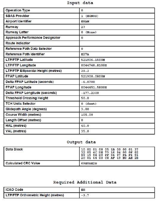
| Serial number |
Path
descriptor |
WPT ident | Fly-over |
Course/Track
°MAG / (°T) |
Recom.
navaid |
Dist. (NM) | Turn | Altitude (FT / FL) |
Speed
(KIAS) |
VPA (°) / TCH (FT) |
NAV
specification |
| 001 | IF | SPL | - | - | - | - | - | + FL 070 | - 220 | - | - |
| 002 | TF | AM280 | - | 226 /
(228.2) |
- | 7.6 | - | - | - | - | RNAV 1 |
| 003 | TF | AM281 | - | 181 /
(183.2) |
- | 7.0 | - | - | - | - | RNAV 1 |
| 004 | TF | AM282 | - | 091 /
(093.2) |
- | 3.3 | - | - | - | - | RNAV 1 |
| 005 | TF | OLGAX | - | 051 /
(053.2) |
- | 2.3 | - | + 2000 | - 220 | - | RNAV 1 |
| 001 | IF | BOVCO | - | - | - | - | - | - | - 220 | - | - |
| 002 | CF | OLGAX | - | 001 /
(003.2) |
MSA | 7.6 | - | + 2000 | - 220 | - | - |
| 001 | IF | OLGAX | - | - | - | - | - | + 2000 | - 220 | - | - |
| 002 | CF | AM632 | - | 001 /
(003.2) |
MSA | 3.2 | - | + 2000 | - | - | - |
| 003 | CF | THR 36C | Y | 001 /
(003.2) |
MSA | 6.2 | - | - | - | -3.00 / 50 | - |
| 004 | CA | - | - | 001 /
(003.2) |
MSA | - | - | @ 2000 | - 220 | - | - |
| Serial number |
Path
descriptor |
WPT ident | Fly-over |
Course/Track
°MAG / (°T) |
Recom.
navaid |
Dist. (NM) | Turn | Altitude (FT / FL) |
Speed
(KIAS) |
VPA (°) / TCH (FT) |
NAV
specification |
| 001 | IF | SPL | - | - | - | - | - | + FL 070 | - 220 | - | - |
| 002 | TF | AM280 | - | 226 /
(228.2) |
- | 7.6 | - | - | - | - | RNAV 1 |
| 003 | TF | AM281 | - | 181 /
(183.2) |
- | 7.0 | - | - | - | - | RNAV 1 |
| 004 | TF | AM282 | - | 091 /
(093.2) |
- | 3.3 | - | - | - | - | RNAV 1 |
| 005 | TF | OLGAX | - | 051 /
(053.2) |
- | 2.3 | - | + 2000 | - 220 | - | RNAV 1 |
| 001 | IF | BOVCO | - | - | - | - | - | - | - 220 | - | - |
| 002 | TF | OLGAX | - | 001 /
(003.2) |
- | 7.6 | - | + 2000 | - 220 | - | RNAV 1 |
| 001 | IF | OLGAX | - | - | - | - | - | + 2000 | - 220 | - | - |
| 002 | TF | AM632 | - | 001 /
(003.2) |
- | 3.2 | - | + 2000 | - | - | RNP APCH |
| 003 | TF | THR 36C | Y | 001 /
(003.2) |
- | 6.2 | - | - | - | -3.00 / 50 | RNP APCH |
| 004 | TF | AM283 | - | 001 /
(003.2) |
- | 13.1 | - | @ 2000 | - 220 | - | RNP APCH |
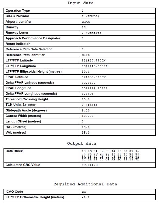
| Serial number |
Path
descriptor |
WPT ident | Fly-over |
Course/Track
°MAG / (°T) |
Recom.
navaid |
Dist. (NM) | Turn | Altitude (FT / FL) |
Speed
(KIAS) |
VPA (°) / TCH (FT) |
NAV
specification |
| 001 | IF | SPL | - | - | - | - | - | + FL 070 | - 220 | - | - |
| 002 | TF | AM160 | - | 136 /
(138.4) |
- | 8.6 | - | - | - | - | RNAV 1 |
| 003 | TF | AM161 | - | 181 /
(183.3) |
- | 7.1 | - | - | - | - | RNAV 1 |
| 004 | TF | AM162 | - | 271 /
(273.3) |
- | 3.2 | - | - | - | - | RNAV 1 |
| 005 | TF | NEWCO | - | 311 /
(313.3) |
- | 2.2 | - | + 2000 | - 220 | - | RNAV 1 |
| 001 | IF | KAROF | - | - | - | - | - | - | - | - | - |
| 002 | CF | NEWCO | - | 001 /
(003.3) |
ABA | 7.6 | - | + 2000 | - 220 | - | - |
| 001 | IF | NEWCO | - | - | - | - | - | + 2000 | - 220 | - | - |
| 002 | CF | AM636 | - | 001 /
(003.3) |
ABA | 3.2 | - | + 2000 | - | - | - |
| 003 | CF | THR 36R | Y | 001 /
(003.3) |
ABA | 6.2 | - | - | - | -3.00 / 50 | - |
| 004 | TF | AM637 | Y | 001 /
(003.3) |
- | 5.0 | - | - 1500 | - | - | RNAV 1 |
| 005 | TF | AM163 | - | 001 /
(003.3) |
- | 7.9 | - | @ 2000 | - 220 | - | RNAV 1 |
| Serial number |
Path
descriptor |
WPT ident | Fly-over |
Course/Track
°MAG / (°T) |
Recom.
navaid |
Dist. (NM) | Turn | Altitude (FT / FL) |
Speed
(KIAS) |
VPA (°) / TCH (FT) |
NAV
specification |
| 001 | IF | ARTIP | - | - | - | - | - | - FL 100
+ FL 070 |
- 250 | - | - |
| 002 | TF | INBAM | - | 228 /
(230.8) |
- | 15.0 | - | - | - | - | RNAV 1 |
| 003 | TF | AM665 | - | 228 /
(230.6) |
- | 10.1 | - | - | - 220 | - | RNAV 1 |
| 004 | TF | AM667 | - | 208 /
(211.0) |
- | 9.5 | - | - | - | - | RNAV 1 |
| 005 | TF | AM668 | - | 268 /
(270.1) |
- | 4.0 | - | - | - 180 | - | RNAV 1 |
| 006 | TF | AM669 | - | 331 /
(333.3) |
- | 3.0 | - | + 2000 | - | - | RNAV 1 |
| 007 | CF | AM636 | Y | 001 /
(003.2) |
ABA | 2.0 | - | + 2000 | - | - | - |
| Serial number |
Path
descriptor |
WPT ident | Fly-over |
Course/Track
°MAG / (°T) |
Recom.
navaid |
Dist. (NM) | Turn | Altitude (FT / FL) |
Speed
(KIAS) |
VPA (°) / TCH (FT) |
NAV
specification |
| 001 | IF | SPL | - | - | - | - | - | + FL 070 | - 220 | - | - |
| 002 | TF | AM160 | - | 136 /
(138.4) |
- | 8.6 | - | - | - | - | RNAV 1 |
| 003 | TF | AM161 | - | 181 /
(183.3) |
- | 7.1 | - | - | - | - | RNAV 1 |
| 004 | TF | AM162 | - | 271 /
(273.3) |
- | 3.2 | - | - | - | - | RNAV 1 |
| 005 | TF | NEWCO | - | 311 /
(313.3) |
- | 2.2 | - | + 2000 | - 220 | - | RNAV 1 |
| 001 | IF | KAROF | - | - | - | - | - | - | - 220 | - | - |
| 002 | TF | NEWCO | - | 001 /
(003.3) |
- | 7.6 | - | + 2000 | - 220 | - | RNAV 1 |
| 001 | IF | NEWCO | - | - | - | - | - | + 2000 | - 220 | - | - |
| 002 | TF | AM636 | - | 001 /
(003.2) |
- | 3.2 | - | + 2000 | - | - | RNP APCH |
| 003 | TF | THR 36R | Y | 001 /
(003.2) |
- | 6.2 | - | - | - | -3.00 / 50 | RNP APCH |
| 004 | TF | AM637 | Y | 001 /
(003.3) |
- | 5.0 | - | - 1500 | - | - | RNP APCH |
| 005 | TF | AM163 | - | 001 /
(003.3) |
- | 7.9 | - | @ 2000 | - 220 | - | RNP APCH |
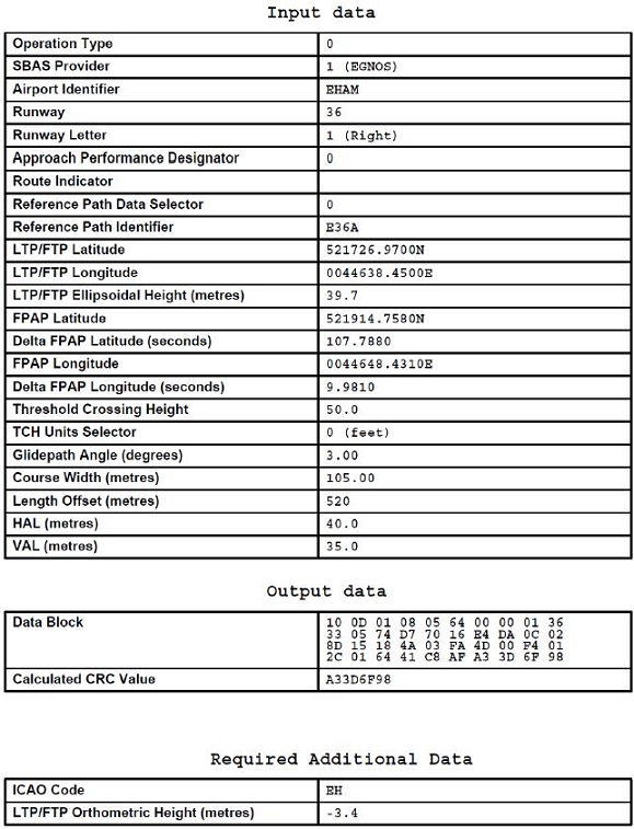
During periods of low visibility the overall ATC capacity is reduced. To guarantee aircraft safety and optimal use of ATC capacity, Schiphol Airport uses ATC low visibility procedures. These procedures are based on ICAO Doc 9476/1 (Surface Movement Guidance and Control Manual) and ICAO EUR Doc 013 (European Guidance Material on All Weather Operations at Aerodromes).
The ATC low visibility operations are categorised in four phases (A, B, C, and D) that are based on RVR values and ceiling.
Phase A is a reduced visibility procedure; phases B, C, and D are low visibility procedures.
The ATC low visibility operations are categorised in four phases (A, B, C, and D) that are based on RVR values and ceiling.
Phase A is a reduced visibility procedure; phases B, C, and D are low visibility procedures.
| Phase | Conditions | Procedures |
| A | RVR <= 1500 M and/or
ceiling <= 300 FT |
Reduced visibility has only impact on ground operations regarding departing traffic (e.g. stop bars are activated and intersection take-offs are not allowed, except for RWY 24 intersection take-off TWY S6 or S8 at ATC discretion). |
| B | RVR < 550 M and/or
ceiling < 200 FT |
Runway use will be restricted. |
| C | RVR < 350 M | Runway use will be restricted. |
| D | RVR < 200 M | Only one runway with ILS CAT III will be AVBL for landing and one runway for departure. |
Note:
if a ground surveillance system and/or the runway stop bars are out of service, additional restrictions apply.
Reduced visibility has only impact on departing traffic, therefore the announcement is only broadcasted on the Departure ATIS.
Pilots should not request start-up permission unless RVR values for the take-off runway are above the flight's take-off limits. Pilots should be informed about the RVR minima that apply to their flights, so that they can readily respond to ATC requests about these minima.
During reduced and low visibility procedures all runway exits, entries and crossings (except RWY 04/22) are safeguarded by switchable (remote controlled) or fixed stop bars (see GMC chart). Crossing of activated stop bars is prohibited. Traffic may proceed only after ATC clearance and when the stop bar lights are switched off (ref Annex 2, item 3.2.2.7.3).
Pilots should not request start-up permission unless RVR values for the take-off runway are above the flight's take-off limits. Pilots should be informed about the RVR minima that apply to their flights, so that they can readily respond to ATC requests about these minima.
During reduced and low visibility procedures all runway exits, entries and crossings (except RWY 04/22) are safeguarded by switchable (remote controlled) or fixed stop bars (see GMC chart). Crossing of activated stop bars is prohibited. Traffic may proceed only after ATC clearance and when the stop bar lights are switched off (ref Annex 2, item 3.2.2.7.3).
During low visibility procedures additional separation on final is applied to ensure the ILS signal integrity.
Taxi guidance based on ground surveillance information will be provided (shared pilot/ATC responsibility for routing and avoidance of inadvertent runway entry).
Inbound aircraft shall be guided by a follow-me car on TWY A1A, A1B, A2 and adjacent aircraft stands.
On the taxiways east of RWY 18L/36R (EXC route via TWY E8, N and N1) aircraft shall be towed or guided by a follow-me car. Therefore the availability of the K-apron for parking and departure operations will depend on the availability of a tow truck or a follow-me car.
Inbound aircraft shall be guided by a follow-me car on TWY A1A, A1B, A2 and adjacent aircraft stands.
On the taxiways east of RWY 18L/36R (EXC route via TWY E8, N and N1) aircraft shall be towed or guided by a follow-me car. Therefore the availability of the K-apron for parking and departure operations will depend on the availability of a tow truck or a follow-me car.
If the RVR values drop below 200 M
and
the ground surveillance infrastructure has degraded to an unacceptable level, the airport will ultimately be closed for all traffic (ATIS RTF: "Schiphol below operational limits").
Non-adherence to the procedures mentioned below leads to an unacceptable load for ATC and may result in the flight being refused to enter the CTR or being instructed to leave the CTR. In these cases the pilot is obliged to inform ATC whether he will hold outside the CTR awaiting (re-)entry clearance or will divert to another aerodrome. In the latter case ATC shall be informed to which aerodrome the aircraft will divert.
Schiphol CTR has been designated as controlled airspace (class C). All VFR flights within Schiphol CTR shall submit a flight plan, which may not be sent by radio.
For the following types of VFR flights:
pilots must obtain (in accordance with the procedures described in paragraph 4.3):
All VFR flights to and from Schiphol airport shall be carried out via the VFR sector (see the charts VAC - VFR procedures and VFR TFC circuits) unless otherwise instructed by ATC or when approved by ATC on pilot's request. All aircraft performing VFR flights in the Schiphol CTR must show their landing lights.
Due to high intensity traffic in the Schiphol CTR, it is strongly advised to avoid the CTR. See also ENR 1.2 paragraph 7. A clearance is required for all flights in the Schiphol CTR and shall depend on weather conditions, runways in use and traffic density (ATC workload).
VFR flights without a mode S transponder will not be admitted to the Schiphol CTR.
VFR flights without a mode S transponder will not be admitted to the Schiphol CTR.
Initial permission for crossing the Schiphol CTR shall be requested by filling out and emailing the online form "Crossing VFR flights Schiphol CTR". Fill out the form, and indicate the route in the CTR on the provided map. Upon receipt and tactical evaluation by ATC, initial permission may be given.
The online form "Crossing VFR flights Schiphol CTR" is published on the LVNL website:
https://en.lvnl.nl/services/vfr-flights-schiphol-ctr (webpage available in Dutch and English).
The form needs to be submitted at least 6 hours before departure. Especially during peak hours, on MON-FRI between 0500-2300 (0400-2200), a clearance is unlikely to be given. A request may receive initial permission, but clearance to enter the CTR will be given upon request via RTF 2 minutes before entry. If initial permission is received, file a flight plan. Clearance shall be based on actual meteorological and operational circumstances. Due to operational circumstances, additional instructions may be given.
The online form "Crossing VFR flights Schiphol CTR" is published on the LVNL website:
https://en.lvnl.nl/services/vfr-flights-schiphol-ctr (webpage available in Dutch and English).
The form needs to be submitted at least 6 hours before departure. Especially during peak hours, on MON-FRI between 0500-2300 (0400-2200), a clearance is unlikely to be given. A request may receive initial permission, but clearance to enter the CTR will be given upon request via RTF 2 minutes before entry. If initial permission is received, file a flight plan. Clearance shall be based on actual meteorological and operational circumstances. Due to operational circumstances, additional instructions may be given.
VFR flights within the CTR may be instructed by ATC to stay clear of specified IFR areas. These areas are indicated on the chart VAC - VFR procedures.
VFR flights with permission to fly over Amsterdam may be instructed by ATC to stay within the Amsterdam sector. This sector is indicated on the chart VAC - VFR procedures.
When issuing the landing clearance, ATC shall inform pilots about the current surface wind direction and speed (including gusts >= 5 KT). When the current surface wind speed is >= 20 KT, ATC shall report this information also on downwind. However, in case RTF load becomes excessive, ATC may not report this information to aircraft facing a crosswind (including gusts) < 20 KT upon landing.
- File a VFR flight plan at least 60 minutes before ETD. Report changes in ETD in excess of 30 minutes to the ATS reporting office (ARO). If ATD is not within 60 minutes after ETD, ATC will consider the flight plan cancelled.
- Pilots must have obtained start-up clearance from ATC before starting engines. A request for start-up shall be made to Schiphol Delivery. Clearance for start-up will either be issued immediately or at a specified time depending on traffic and/or main runway(s) in use. A request for start-up shall include:
Note:
K-apron is not under ATC ground control. At apron exit GD pilots shall report to Schiphol Ground.
- File a VFR flight plan at aerodrome of departure at least 60 minutes before ETD. Report changes in ETD in excess of 30 minutes to the ATS reporting office (ARO). To prevent unnecessary alerting action, attention is drawn to importance of the ETA to be as accurate as possible and to report changes in ETA in excess of 30 minutes to the relevant FIC.
- Contact Schiphol TWR 2 minutes before reaching the CTR boundary for permission to enter the CTR (abbreviated phraseology: aircraft identification and type, VFR to Schiphol, estimating VICTOR at ....., ATIS information, for landing).
- Pilots may be instructed to contact Schiphol Approach, Schiphol Arrival or Schiphol Departure for radar control.
- Approach the airport via the VFR sector at 1000 FT AMSL or below and report over VICTOR.
- VICTOR, ALPHA (abeam Nes a/d Amstel) and BRAVO (abeam church Bovenkerk) may be used as visual holding point for orbits (360° turn over left).
- Execute a normal circuit unless a short VFR approach pattern (threshold base leg or mid runway base leg) is required by ATC or when approved on pilot's request.
The short VFR approach patterns (threshold base leg and mid runway base leg) are based on a maximum TAS of 120 KT and "rate 2" turns. They are established to avoid traffic operation on other runways, to expedite traffic and for noise abatement purposes. The short VFR circuit procedures shall be carried out as follows:
- Select transponder code 7600.
-
If possible call Amsterdam ACC Supervisor on telephone number +31 (0)20 406 3999.
Note: use telephone connection to mitigate COM failure only. All telephone calls will be automatically recorded. - If telephone connection is disconnected prematurely (before read-back), revert to communication failure procedures below.
In case of communication failure adhere to the departure instructions. If the departure instructions contain a clearance limit in the CTR, act in accordance with paragraph 4.4.4.
- In case of communication failure before joining the circuit, leave the CTR according to VICTOR Departure and divert to an appropriate aerodrome.
- In case of communication failure over or after a position from where to join the circuit (this is past the compulsory reporting point BRAVO), execute a circuit as short as practicable for the last received and acknowledged runway (helispot). If the runway appears to be clear, make a full stop landing and vacate as soon as possible, otherwise go around and execute a similar circuit (be aware of the fact that your flight path could interfere with the flight path of other aerodrome traffic).
- In case of communication failure before joining the circuit, act in accordance with paragraph 4.4.4.
- In case of communication failure after joining the circuit, act in accordance with paragraph 4.4.3.1 item b.
- In case of communication failure overhead the centre of the aerodrome, maintain altitude, proceed to point BRAVO, act in accordance with paragraph 4.4.3.1 item a.
In case of communication failure leave the CTR via the shortest route (radial wise), maintain altitude until outside the CTR, do not cross a runway centre line or IFR area and proceed to an appropriate aerodrome.
1. Due to approaching IFR traffic the execution of VFR flights in the direct vicinity of the Schiphol CTR shall be avoided as much as possible (see ENR 1.2). Pilots are strongly recommended to use the frequency monitoring code as outlined in ENR 1.2.
2. Pilots shall be aware that in the vicinity of the aerodrome, ATC gives priority to:
- aircraft in state of an emergency;
- hospital and police aircraft with the status priority or scramble;
- aircraft engaged in SAR operations.
3. Bird-scare patrols are active 24 hours a day and use various equipment, including flare shellcrackers, alternating bird dispersal guns and amplified cries of distress.
4. When lightning discharges are observed in the vicinity of the airport, the flow manager aircraft will announce that all ground handling and re-fuelling operations are prohibited until further notice. When it is safe to do so, the flow manager aircraft will declare that ground handling and re-fuelling operations can be resumed.
5. Before taxiing to RWY
2. Pilots shall be aware that in the vicinity of the aerodrome, ATC gives priority to:
- aircraft in state of an emergency;
- hospital and police aircraft with the status priority or scramble;
- aircraft engaged in SAR operations.
3. Bird-scare patrols are active 24 hours a day and use various equipment, including flare shellcrackers, alternating bird dispersal guns and amplified cries of distress.
4. When lightning discharges are observed in the vicinity of the airport, the flow manager aircraft will announce that all ground handling and re-fuelling operations are prohibited until further notice. When it is safe to do so, the flow manager aircraft will declare that ground handling and re-fuelling operations can be resumed.
5. Before taxiing to RWY
In the table below the functions of all taxiways connected to a runway are indicated when present and marked with "L" or "U" depending on the availability of centre line lights.
| Runway | Taxiway | Function | Remarks | |||
|
Rapid exit
taxiway* |
Exit
taxiway |
Take-off
intersection |
Runway
crossing |
|||
| 04/22 | G1 | - | U | U | - | TWY width 15 M.
MAX wingspan 31 M. |
| G2 | - | U | U | U | - | |
| G3 | - | U | - | - | No-entry from TWY G. | |
| G4 | - | U | - | U | - | |
| G5 | - | U | U | U | - | |
| G6 | - | U | - | U | - | |
| G7 | - | U | - | U | TWY L width 20 M.
MAX wingspan 36 M. |
|
| G8 | - | - | - | U | - | |
| 06/24 | S1 | - | L | L 1) | L | 1) TWY CL LGT interrupted when diverging from the straight section of TWY S1 towards the RWY CL. |
| S2 | - | L | - | L | - | |
| S3 |
|
U 1) | U 2) | - |
1) Exit from RWY 24 MAX wingspan 36 M.
2) From TWY B right turn to RWY 24 MAX wingspan 36 M. |
|
| S4 |
|
U 1) | U 2) | - |
1) Exit from RWY 24 MAX wingspan 36 M.
2) From TWY B right turn to RWY 24 MAX wingspan 36 M. |
|
| S5 | - | - | U | - | From TWY B right turn to RWY 24 MAX wingspan
36 M. |
|
| S6 |
|
- | L | - | - | |
| S7E | - | L | L | - | - | |
| S7W | - | - | - | L | - | |
| S8 | - | L | L | L | - | |
| S9 | - | - | - | L | - | |
| S10 | - | L | L 1) | L | 1) TWY CL LGT interrupted when diverging from the straight section of TWY S10 towards the RWY CL. | |
| 09/27 | N1 | - | L | L | - | - |
| N2 |
|
- | - | L | - | |
| N3 |
|
- | U | - | - | |
| N4 |
|
- | U | - | - | |
| N5 | - | L | L | - | - | |
| N9 |
|
- | - | - | No-entry from TWY B. | |
| 18C/36C | W1 | - | L | L | - | - |
| W2 | - | L | U | - | - | |
| W3 |
|
- | U | - | - | |
| W4 |
|
- | U | - | - | |
| W5 | - | L 1) | U 2) | L |
1) Exit RWY 36C.
2) Take-off entry RWY 18C. |
|
| W6 |
|
U 1)2) | - | - |
1) Exit from RWY 36C MAX wingspan 36 M.
2) No-entry from TWY B. |
|
| W7 |
|
- | U | - | - | |
| W8 |
|
- | U | - | - | |
| W9 | - | U | U | - | - | |
| W10 | - | L | L | - | - | |
| W11 | - | U | L | - | - | |
| W12 | - | U | U | - | - | |
| W13 | - | - | - | L | - | |
| 18L/36R | E1 |
|
- | - | - | No-entry from TWY B. |
| E2 |
|
- | U | - | - | |
| E3 | - | - | - | U | - | |
| E4 | - | U | U | L | - | |
| E5 | - | L | U | U | - | |
| E6 | - | - | L | - | - | |
| E7 | - | - | - | U | - | |
| E8 | - | U 1) | U 1) | L | 1) MAX wingspan 36 M due to TWY curve. | |
| E9 | - | - | - | U | - | |
| E10 | - | U 1) | - | U | 1) MAX wingspan 36 M due to TWY curve. | |
| 18R/36L | V1 |
|
- | U | - | - |
| V2 |
|
- | U | - | - | |
| V3 | - | L | U | - | - | |
| V4 | - | L | L | - | - | |
|
U = no taxiway centre line lights |
||||||
* Rapid exit taxiways angle and radius of turn-off:
| RWY | Rapid exit TWY | Intersection angle (°) | Radius of turn-off (M) | Remarks |
| 06 | S3 | 30 | 320 | - |
| S4 | 30 | 315 | - | |
| S6 | 30 | 350 | - | |
| 09 | N9 | 30 | 310 | - |
| 18C | W6 | 30 | 350 | - |
| W7 | 30 | 350 | - | |
| W8 | 30 | 350 | - | |
| 18R | V1 | 30 | 550 | Caution: V3 is no rapid exit taxiway. |
| V2 | 30 | 550 | ||
| 27 | N2 | 30 | 330 | - |
| N3 | 30 | 310 | - | |
| N4 | 30 | 325 | - | |
| 36C | W4 | 30 | 550 | - |
| W3 | 30 | 550 | - | |
| 36R | E1 | 30 | 310 | - |
| E2 | 30 | 300 | - |
RWY 04/22 primarily serves as a runway for general aviation. In certain circumstances, i.e. southwesterly storm, RWY 22 also serves as secondary or even main landing runway for commercial air transport up to and including code letter E aircraft.
RWY 04/22 has the following specific features:
- Although equipped with ILS (CAT I), RWY 22 is classified as non-precision approach runway. Because of this runway classification, the minimum DH for all types of approaches (ILS and/or RNP) is 250 FT. EU-law only allows type A instrument approach operations on a non-precision approach runway.
- The length of the approach lighting system of RWY 04 and RWY 22 is less than those installed on other runways (see AD 2.14).
- The MEHT of the PAPI of RWY 04 and RWY 22 is less than the MEHT of other PAPIs (see AD 2.14).
The reduced MEHT means the minimum required 6 M wheel height over THR for aircraft with an eye-to-wheel height of 8 to 14 M cannot be guaranteed, depending on the type of aircraft.
- Runway centre line lights and touchdown zone lights are not provided (see AD 2.14).
- During approach RWY 04 or RWY 22 pilots must be prepared for turbulence, windshear and change of wind gradient (possibly simultaneously) due to the presence of large buildings and an engine run-up area underneath the circuits.
- During approach RWY 04 or RWY 22 pilots must not confuse the runway with parallel TWY G situated east of RWY 04/22.
- Vacating RWY 04 via TWY G1 is restricted to aircraft with a maximum wingspan of 31 M due to wingspan restriction on adjacent taxiways.
- All runway exits have a 90° angle reference to the runway centre line; larger aircraft are advised to exercise caution when vacating the runway.
- See AD 2.23 paragraph 2 for more information on runway exits.
- Although equipped with ILS (CAT I), RWY 22 is classified as non-precision approach runway. Because of this runway classification, the minimum DH for all types of approaches (ILS and/or RNP) is 250 FT. EU-law only allows type A instrument approach operations on a non-precision approach runway.
- The length of the approach lighting system of RWY 04 and RWY 22 is less than those installed on other runways (see AD 2.14).
- The MEHT of the PAPI of RWY 04 and RWY 22 is less than the MEHT of other PAPIs (see AD 2.14).
The reduced MEHT means the minimum required 6 M wheel height over THR for aircraft with an eye-to-wheel height of 8 to 14 M cannot be guaranteed, depending on the type of aircraft.
- Runway centre line lights and touchdown zone lights are not provided (see AD 2.14).
- During approach RWY 04 or RWY 22 pilots must be prepared for turbulence, windshear and change of wind gradient (possibly simultaneously) due to the presence of large buildings and an engine run-up area underneath the circuits.
- During approach RWY 04 or RWY 22 pilots must not confuse the runway with parallel TWY G situated east of RWY 04/22.
- Vacating RWY 04 via TWY G1 is restricted to aircraft with a maximum wingspan of 31 M due to wingspan restriction on adjacent taxiways.
- All runway exits have a 90° angle reference to the runway centre line; larger aircraft are advised to exercise caution when vacating the runway.
- See AD 2.23 paragraph 2 for more information on runway exits.
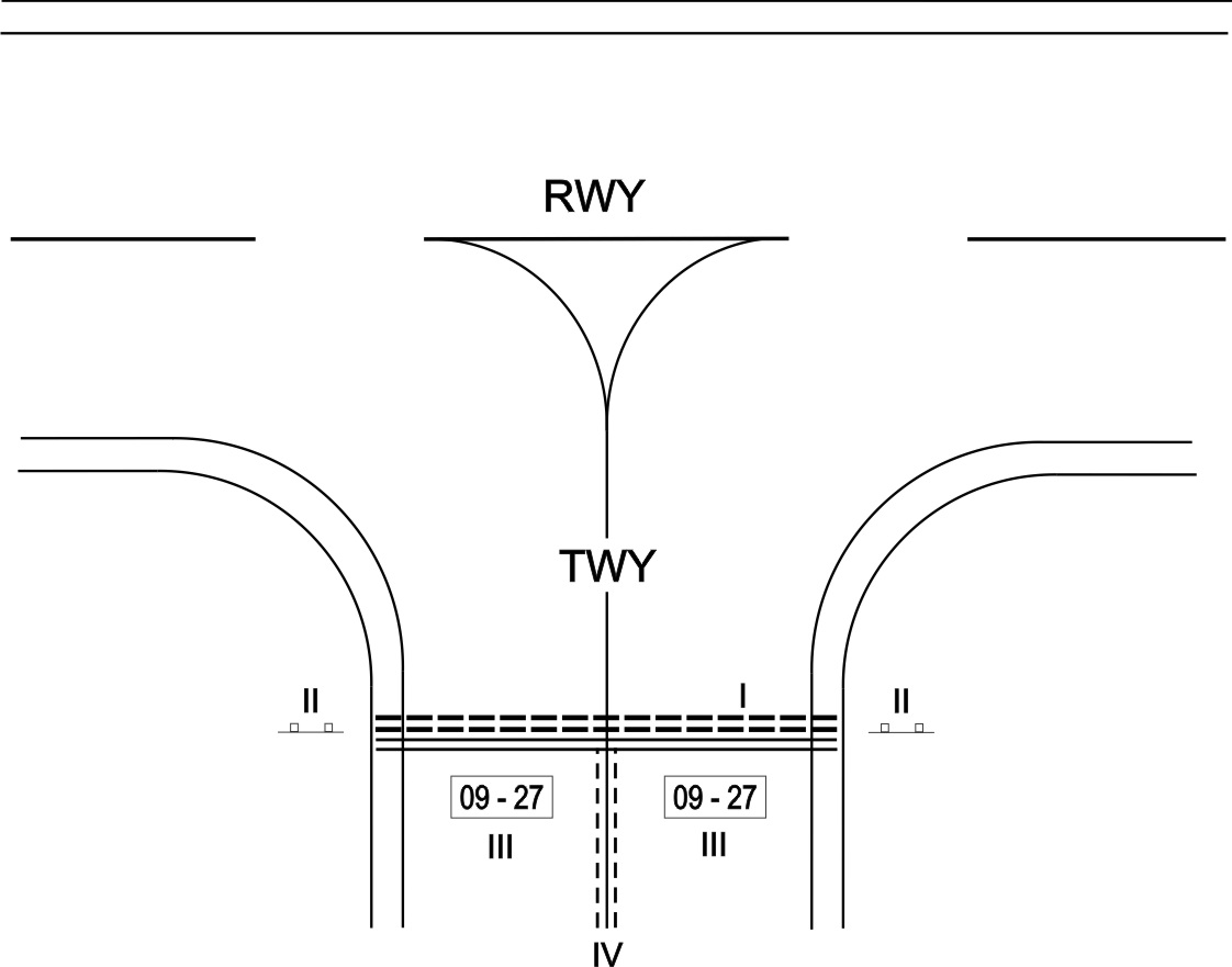
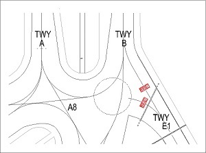
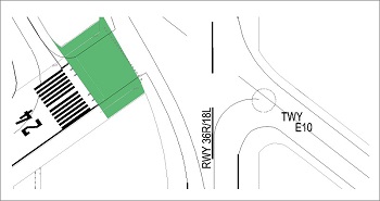
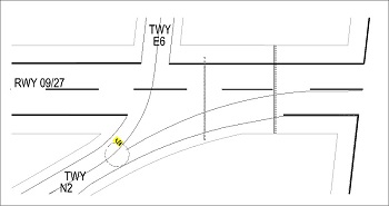
The datum line from which the reduced runway declared distances for take-off should be determined is defined by the intersection of the downwind edge of the specific taxiway with the runway edge as shown in the diagram below. The loss of runway length due to alignment of the aircraft prior to take-off should be taken into account by the operators for the calculation of the aircraft’s take-off mass (ICAO Annex 6, Part 1, paragraph 5.2.8).
If an intersection take-off will take place from an intersection with an intersection angle of 30° (rapid exit taxiway), and the taxiway centre line is followed until the runway centre line, there is a loss of line-up distance of at least 200 M.
If an intersection take-off will take place from an intersection with an intersection angle of 30° (rapid exit taxiway), and the taxiway centre line is followed until the runway centre line, there is a loss of line-up distance of at least 200 M.
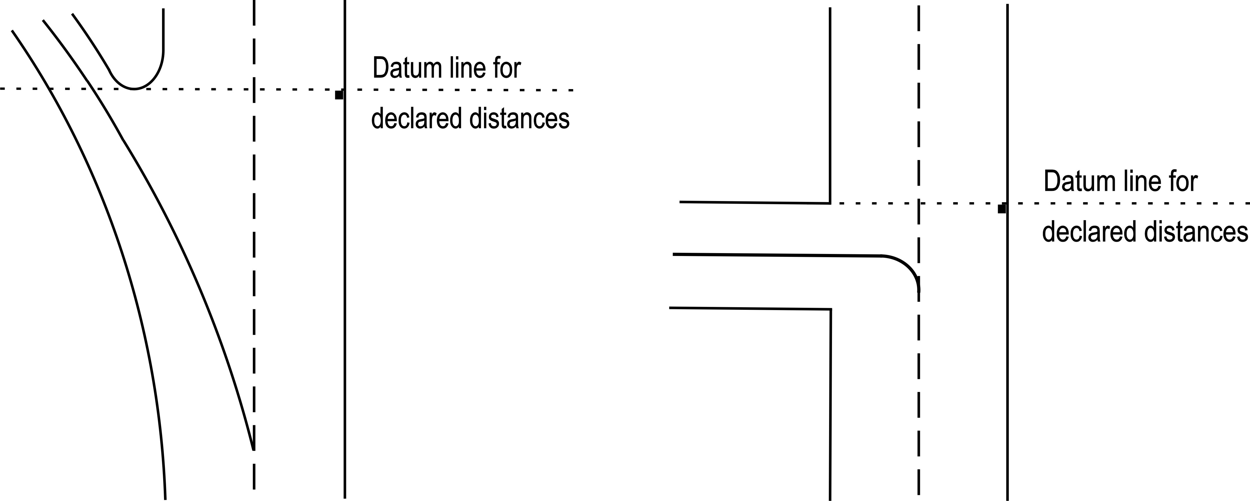
Normal operations at Schiphol Airport do not require a turn pad, therefore runway turn pads, designed according to international requirements are not provided. Instead turn-around areas are provided at the end of RWY 24 and RWY 36L.
Both turn-around areas are designed using a nose wheel steering angle of more than 45 degrees. Guidance for the use of both turn-around areas is provided by a yellow guidance line. Inset edge lights are provided at the boundary of the runway and the full strength shoulder within the turn-around area. No additional guidance lights are provided. Marshaller guidance is required for aircraft with wingspan 36 M, or greater, or at ATC discretion, and available on pilot’s request.
Runway shoulders within the turn-around area are reinforced and provide the same strength as the related runway pavement. Width of the runway turn-around area including runway shoulders is 75 M.
Note:
for code letter E and F aircraft the use of differential braking and asymmetric power to make a 180 degree turn within the turn-around area may be necessary.
Both turn-around areas are designed using a nose wheel steering angle of more than 45 degrees. Guidance for the use of both turn-around areas is provided by a yellow guidance line. Inset edge lights are provided at the boundary of the runway and the full strength shoulder within the turn-around area. No additional guidance lights are provided. Marshaller guidance is required for aircraft with wingspan 36 M, or greater, or at ATC discretion, and available on pilot’s request.
Runway shoulders within the turn-around area are reinforced and provide the same strength as the related runway pavement. Width of the runway turn-around area including runway shoulders is 75 M.
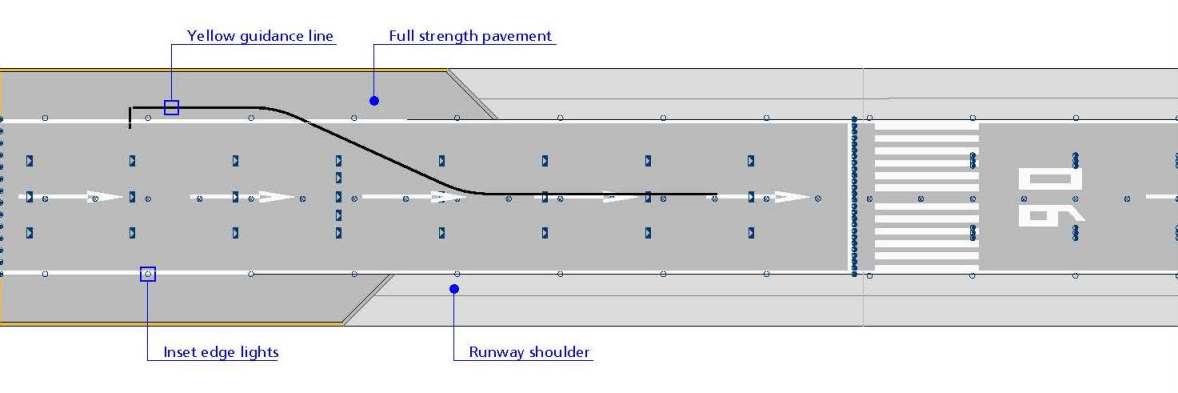
No turn-around area is provided at the end of RWY 18L. Marshaller guidance is required for aircraft with wingspan 36 M or greater and available on pilot’s request. A tow truck is required for EASA code letter F aircraft, or at ATC discretion.
ATIS (ARR and DEP) via datalink (ARINC / SITA) is available. Aircraft equipped with ACARS compliant with ARINC 622 and 623 specifications will be able to use the datalink service. If unsuccessful revert to ATIS voice broadcast and inform the SITA or ARINC provider. In case of system failure, contact the appropriate SITA or ARINC helpdesk or your customer support account team.
Operational restrictions on code letter F aircraft are shown on charts GMC A380 restrictions, GMC AN124 restrictions and GMC B747-8 restrictions; see EHAM AD 2.24.
Additional details are shown in the table below. The restrictions per aircraft type are marked with an X. A dash indicates no restrictions.
Additional details are shown in the table below. The restrictions per aircraft type are marked with an X. A dash indicates no restrictions.
| Restrictions | Airbus A380 | Antonov AN124 | Boeing 747-8 |
|---|---|---|---|
| ILS landings | |||
| All RWYs: ILS landings shall be made with coupled autopilot or flight director mode to ensure maximum track-accuracy to the runway centre line (see ICAO Circular 301). | X | - | - |
| Runways | |||
| RWY 04/22: use of RWY prohibited due to insufficient runway width. | X | X | X |
| RWY 06/24: use of turn around area RWY end 24 under marshaller guidance only. | X | X | X |
| RWY 18R/36L: use of turn around area RWY end 36L under marshaller guidance only. | X | X | X |
| RWY 18L/36R: turn around on RWY end 18L not possible, towing required. | X | X | X |
| Taxiways and aprons | |||
| TWY R between aircraft stand R77 and TWY B: access only under marshaller guidance. | X | X | - |
| TWY A and TWY B between A28 and AS/BS: thrust on outer engines limited to MAX ground idle power due to highway bridge. | X | X | - |
| TWY S: access only under marshaller guidance. Prohibited for use by Airbus A380. | X | X | - |
| Apron TWY A13 abeam aircraft stands numbered lower than E18: access prohibited due to wingspan restrictions. | X | X | X |
| Apron TWY A19C abeam aircraft stands numbered lower than G9: access prohibited due to wingspan restrictions. | X | X | X |
| Aircraft stands (related to parking purposes only) | |||
| E18: arriving A380 will be parked on P3 and towed to E18. Prohibited for use by AN124. | X | X | - |
| Remote de-icing facilities | |||
| Remote de-icing spot P10 access prohibited due to wingspan restrictions. | X | X | - |
| Remote de-icing spot P12 access prohibited due to wingspan restrictions. | X | X | X |
| Remote holding positions | |||
| Remote holding position P1: access prohibited due to wingspan restrictions. | X | X | - |
| Remote holding position P2: access prohibited due to wingspan restrictions. | X | X | X |
| Remote holding positions PA, PB, PC and PD: access prohibited due to wingspan restrictions. | X | X | X |
| Remote holding positions P20, P21, P22 and P23: access prohibited due to wingspan restrictions. | X | X | X |
| Remote holding positions P6A, P6B, P7A and P7B: access prohibited due to wingspan restrictions. | X | X | X |
| Engine run-up facilities | |||
| Engine run-up area (towing only): no access due to wingspan restrictions. | X | - | - |
To minimise taxi times and to protect the ILS LOC critical area, pilots of Airbus A380 equipped with a brake-to-vacate system are advised to select the following exits, unless instructed otherwise:
To protect the ILS LOC sensitive area, pilots shall vacate the exit taxiway completely onto the taxiway parallel to the runway as soon as practicable.
This procedure is developed in order to provide clarity about conditions and service provision in case of a "minimum fuel" call.
Operators with aircraft in a (potential) minimum fuel situation may contact Amsterdam FMP to obtain information whether delay can be expected additional to available information (for address see ENR 1.9 paragraph 2.2).
Note:
mentioning a minimum fuel situation to the FMP has no status. Requests for priority handling will not be accepted by the FMP.
- Pilots shall advise "minimum fuel" to ATC when the aircraft's fuel supply has reached a state where the flight is committed to land at a specific aerodrome and no additional delay can be accepted.
- ATC shall use this as advisory information which indicates that an emergency situation is possible, should any undue delay occur. The minimum fuel advisory implies no emergency situation and priority handling will not be provided.
- Amsterdam ACC will provide an expected approach time (EAT) or advise "no delay". No delay means that the anticipated delay before or at the initial approach fix is not more than 2 minutes.
- On request Schiphol APP can provide the approximate distance to touchdown.
Pilots shall declare a medical emergency to ATC only in case of a patient on board suffering from a life-threatening condition. A patient's medical condition is categorised and should be handled as follows:
- Medical emergency (life-threatening): pilots shall contact ATC to declare a medical emergency by radio call prefixed by PAN PAN (3X) for urgency. Priority handling will be provided. Airport authority and medical crew will board the aircraft before passengers disembark.
- Medical care at the gate (non-life-threatening): flight crew shall contact ground handler only to arrange medical crew at the gate.
- Medical meet and assist (non-life-threatening, medical check at first-aid post): flight crew shall contact ground handler only to arrange medical assistance at the gate.
| 1. Cargo handling Schiphol | |
| Post: |
Airport Cargo Handling B.V.
(second line cargo handling)
Snipweg 101 1118 DP Schiphol-South |
| TEL: | +31 (0)20 316 5396 |
| FAX: | +31 (0)20 316 5461 |
| email: | [email protected] |
| SITA: | SPLFLXH |
| Post: |
dnata B.V.
(Cargo & full freighter handling)
Rangoonweg 11 1118 LP Schiphol |
| TEL: | +31 (0)20 603 2569 |
| FAX: | +31 (0)20 603 2329 |
| Email: | [email protected] |
| AFS: | EHAMYIAG |
| SITA: | AMSAFXH |
| Note: | dnata cargo Amsterdam channel 131.855. |
| Post: |
Fr8
(Cargo & full freighter ramp handling by Menzies Aviation Group (Netherlands) B.V.)
Cargo Terminal 8 Anchoragelaan 50 1118 LE Schiphol-Southeast |
| TEL: | +31 (0)20 405 7333 |
| FAX: | +31 (0)20 405 7444 |
| Email: | [email protected] |
| SITA: | SPLAEXH |
| Post: |
Skylink Handling Services B.V.
Anchoragelaan 36 1118 LD Schiphol-Southeast |
| TEL: | +31 (0)20 405 9725 |
| FAX: | +31 (0)20 405 9720 |
| Email: | [email protected] |
| SITA: | SPLCXXH |
| 2. Ground Handling Schiphol-Centre | |
| Post: |
Aviapartner B.V.
Thermiekstraat 16 1117 BC Schiphol Oost |
| TEL: | +31 (0)20 406 7780 |
| Email: | [email protected] |
| SITA: | AMSOVXH |
| Note: | Aviapartner Amsterdam 131.580. |
| Post: |
dnata B.V.
(Passenger services & aircraft handling)
Rangoonweg 11 1118 LP Schiphol |
| TEL: | +31 (0)20 333 9900 |
| Email: | [email protected] |
| SITA: | AMSDOXH |
| Note: | dnata Amsterdam channel 131.410. |
| Post: |
KLM Ground Services
Havenmeesterweg 5-41 1118 CB Schiphol Centrum |
| TEL: | +31 (0)20 304 1400 |
| Email: | [email protected] |
| URL: | https://www.klm.com |
| SITA: | HCT-DTM |
| Note: | KLM Ground Services 131.430. |
| Post: |
Menzies Aviation B.V.
P.O. Box 75625 1118 ZR Schiphol-Centre |
| TEL: | +31 (0)20 446 6430 |
| Email: | [email protected] |
| URL: | https://www.menziesaviation.com |
| AFS: | EHAMYIOA |
| SITA: | AMSOOXH |
| Note: | Menzies Ops 131.805. |
| Post: |
Swissport Amsterdam
P.O. Box 75724 1118 ZT Schiphol-Centre |
| TEL: | +31 (0)20 795 2480 |
| FAX: | +31 (0)20 795 2492 |
| Email: | [email protected] |
| AFS: | EHAMYIGG |
| SITA: | SPLAPXH |
| Note: | Swissport Amsterdam 131.560. |
| Post: |
Viggo Schiphol B.V.
Jan Hilgersweg 2 5657 ES Eindhoven |
| TEL: | +31 (0) 20 211 7510 |
| Email: | [email protected] |
| SITA: | AMSVSXH |
| URL: | https://www.viggo.eu |
| Note: | Viggo Amsterdam channel 131.590. |
| 3. Ground Handling Schiphol-East (General Aviation) | |
| Post: |
Aviapartner Executive
Thermiekstraat 16 1117 BC Schiphol |
| TEL: | +31 (0)20 206 6780 |
| FAX: | +31 (0)20 206 6790 |
| email: | [email protected] |
| URL: | https://www.aviapartner.aero |
| Note: | Aviapartner 131.605. |
| Post: |
Jet Aviation Netherlands
Thermiekstraat 14 1117 BC Schiphol-Oost |
| TEL: | +31 (0)20 226 0150 |
| FAX: | +31 (0)20 648 8180 |
| Email: | [email protected] |
| URL: | https://www.jetaviation.com |
| Note: | Jet Aviation Amsterdam 131.630. |
|
Charts
|
Pages
|
|---|---|
|
ADC
|

|
|
APDC Schiphol Centre
|
|
|
APDC Schiphol East K-apron
|
|
|
APDC Schiphol East M-apron
|
|
|
APDC Schiphol Centre U-apron
|
|
|
GMC
|
|
|
GMC A380 restrictions
|
|
|
GMC AN124 restrictions
|
|
|
GMC B747-8 restrictions
|
|
|
AOC type A RWY 04-22
|
|
|
AOC type A RWY 06-24
|
|
|
AOC type A RWY 09-27
|
|
|
AOC type A RWY 18C-36C
|
|
|
AOC type A RWY 18L
|
|
|
AOC type A RWY 36L
|
|
|
PATC RWY 06
|
|
|
PATC RWY 18C
|
|
|
PATC RWY 18R
|
|
|
PATC RWY 27
|
|
|
PATC RWY 36C
|
|
|
PATC RWY 36R
|
|
|
SID
|
|
|
SID RWY 04
|
|
|
SID RWY 06
|
|
|
SID RWY 06 supplementary
|
|
|
SID RWY 09
|
|
|
SID RWY 18C
|
|
|
SID RWY 18L east
|
|
|
SID RWY 18L west
|
|
|
SID RWY 22
|
|
|
SID RWY 24 east
|
|
|
SID RWY 24 west
|
|
|
SID RWY 27
|
|
|
SID RWY 36C
|
|
|
SID RWY 36L
|
|
|
SID RWY 36L supplementary
|
|
|
STAR
|
|
|
Night transition to ILS RWY 06
|
|
|
Night transition to RNP RWY 06
|
|
|
Night transition to ILS RWY 18C
|
|
|
Night transition to RNP RWY 18C
|
|
|
Night transition to ILS RWY 18R
|
|
|
Night transition to RNP RWY 18R
|
|
|
RNAV transition RWY 36R
|
|
|
ATCSMAC
|
|
|
IAC RNP RWY 04
|
|
|
IAC ILS CAT II & III or LOC RWY 06
|
|
|
IAC RNP RWY 06
|
|
|
IAC RNP RWY 09
|
|
|
IAC ILS CAT II & III or LOC RWY 18C
|
|
|
IAC RNP RWY 18C
|
|
|
IAC ILS CAT II & III or LOC RWY 18R
|
|
|
IAC RNP RWY 18R
|
|
|
IAC ILS or LOC RWY 22
|
|
|
IAC ILS or LOC RWY 22 CAT H
|
|
|
IAC RNP RWY 22
|
|
|
IAC RNP RWY 24
|
|
|
IAC ILS CAT II & III or LOC RWY 27
|
|
|
IAC RNP RWY 27
|
|
|
IAC ILS CAT II & III or LOC RWY 36C
|
|
|
IAC RNP RWY 36C
|
|
|
IAC ILS CAT II & III or LOC RWY 36R
|
|
|
IAC RNP RWY 36R
|
|
|
VAC - VFR procedures
|
|
|
VFR TFC circuits
|
|
To be developed.