EHGG AD 2.1 AERODROME LOCATION INDICATOR AND NAME
|
|
|
|
EHGG AD 2.2 AERODROME GEOGRAPHICAL AND ADMINISTRATIVE DATA
|
|
1
|
ARP coordinates and site at AD
|
530730N 0063500E
216 DEG GEO 499 M from TWR.
|
2
|
Direction and distance from (city)
|
4.8 NM S of Groningen.
|
3
|
Elevation / reference temperature
|
ELEV: 18 FT AMSL / T: 20.9 °C
|
4
|
Geoid undulation at AD ELEV PSN
|
135 FT
|
5
|
MAG VAR / annual change
|
3° E (2025) / 0.2° E
|
6
|
AD operator, address, telephone, telefax, email address, AFS, URL
|
GRONINGEN AIRPORT EELDE
P.O. BOX 50
9765 ZH PATERSWOLDE
THE NETHERLANDS
TEL: +31 (0)50 309 7070
TEL: +31 (0)50 309 7014 (AIRPORT AUTHORITY)
TEL: +31 (0)50 309 7016 (ONLY OUTSIDE OPR HR FOR EMERGENCIES AND MEDICAL FLIGHTS)
email: [email protected]
URL: https://www.groningenairport.nl
|
7
|
Types of traffic permitted (IFR/VFR)
|
IFR/VFR
|
8
|
Remarks
|
NIL
|
|
EHGG AD 2.3 OPERATIONAL HOURS
|
|
1
|
AD operator
|
MON-FRI 0530-2200 (MON-FRI 0430-2100)
SAT SUN HOL 0630-2100 (SAT SUN HOL 0530-2000)
|
2
|
Customs and immigration
|
MON-FRI 0530-2200 (MON-FRI 0430-2100)
SAT SUN HOL 0630-2100 (SAT SUN HOL 0530-2000)
|
3
|
Health and sanitation
|
AVBL
|
4
|
AIS briefing office
|
H24
|
5
|
ATS reporting office (ARO)
|
H24
|
6
|
MET briefing office
|
H24
|
7
|
ATS
|
MON-FRI 0530-2200 (MON-FRI 0430-2100)
SAT SUN HOL 0630-2100 (SAT SUN HOL 0530-2000)
|
8
|
Fuelling
|
MON-FRI 0530-2200 (MON-FRI 0430-2100)
SAT SUN HOL 0630-2100 (SAT SUN HOL 0530-2000)
|
9
|
Handling
|
MON-FRI 0530-2200 (MON-FRI 0430-2100)
SAT SUN HOL 0630-2100 (SAT SUN HOL 0530-2000)
|
10
|
Security
|
MON-FRI 0530-2200 (MON-FRI 0430-2100)
SAT SUN HOL 0630-2100 (SAT SUN HOL 0530-2000)
|
11
|
De-icing
|
MON-FRI 0530-2200 (MON-FRI 0430-2100)
SAT SUN HOL 0630-2100 (SAT SUN HOL 0530-2000)
|
12
|
Remarks
|
AD operator
- For emergency and medical flights only: H24.
- MIL flights PPR from airport authority.
Customs and immigration
- Customs: limited AVBL; during AD OPR HR 3 HR PN, TEL +31 (0)88 622 3100.
Health and sanitation
- PN
MET briefing office
- Outside OPR HR: MWO De Bilt (see EHGG AD 2.11).
Handling
- Compulsory for visiting ACFT MTOM >= 3000 KG, for details see EHGG AD 2.23.
PN means permission from and/or in case of customs etc. notification other than by (VFR) flight plan to aerodrome authority as appropriate.
|
|
EHGG AD 2.4 HANDLING SERVICES AND FACILITIES
|
|
1
|
Cargo-handling facilities
|
AVBL
|
2
|
Fuel / oil types
|
Fuel: JET A-1, AVGAS 100LL
Oil: NIL
|
3
|
Fuelling facilities/capacity
|
Jet A-1: self-service; ACFT with wingspan < 15 M must use self-service; payment only via credit card or Shell carnet at fuel station terminal.
2 trucks.
AVGAS 100LL: self-service; payment only via credit card or Shell carnet at fuel station terminal.
|
4
|
De-icing facilities
|
Equipment AVBL, Type II de-icing fluid ABC-K Plus.
|
5
|
Hangar space for visiting aircraft
|
Light aircraft only.
|
6
|
Repair facilities for visiting aircraft
|
General Enterprises, TEL: +31 (0)50 309 6060.
|
7
|
Remarks
|
Cargo-handling facilities
- See EHGG AD 2.23.
|
|
EHGG AD 2.5 PASSENGER FACILITIES
|
|
1
|
Hotels
|
In Groningen, Eelde and Haren.
|
2
|
Restaurants
|
At the airport (116 seats) and unlimited in Groningen.
|
3
|
Transportation
|
Buses, taxis and rental cars.
|
4
|
Medical facilities
|
First aid treatment; hospitals in Groningen and Assen.
|
5
|
Bank and post office
|
Bank: Cashpoint in terminal building.
Post: NIL
|
6
|
Tourist office
|
NIL
|
7
|
Remarks
|
NIL
|
|
EHGG AD 2.6 RESCUE AND FIREFIGHTING SERVICES
|
|
1
|
AD category for firefighting
|
CAT 5
|
2
|
Rescue equipment
|
3 crash-tenders with portable hydraulic rescue tools and mobile lighting.
|
3
|
Capability for removal of disabled aircraft
|
Cranes AVBL via contractors.
|
4
|
Remarks
|
AD category for firefighting
- CAT 6, 7, 8 and 9 AVBL O/R (24 HR PN).
- For emergency and medical flights outside operational hours CAT 3 is AVBL.
- 3 crash-tenders.
|
|
EHGG AD 2.7 RUNWAY SURFACE CONDITION ASSESSMENT AND REPORTING, AND SNOW PLAN
|
|
1
|
Types of clearing equipment
|
3 snowsweep combinations with ploughs, 1 snowblower, 1 spray vehicle.
|
2
|
Clearance priorities
|
RWY, TWY and apron simultaneously.
|
3
|
Use of material for movement area surface treatment
|
Chemical treatment of runway surface by KFOR. NAAC only locally used at aprons.
|
4
|
Specially prepared winter runways
|
NIL
|
5
|
Remarks
|
1. Responsible authority: airport authority.
2. No specially prepared winter runways AVBL.
3. Methods of snow removal: snowploughs and sweeping machines.
4. Chemical treatment of runway surface by KFOR. NAAC only locally used at aprons.
5. Assessment and measuring of contamination: observation by own experienced staff.
6. Runway condition is determined and reported according to the global reporting format and broadcast via ATIS.
7. Information of the runway condition is published by:
a. SNOWTAM via the international NOTAM office at Schiphol.
b. RCR via ATIS and RTF on TWR frequency.
|
|
EHGG AD 2.8 APRONS, TAXIWAYS AND CHECK LOCATIONS/POSITIONS DATA
|
|
1
|
Apron designation, surface and strength
|
A-apron
|
|
Concrete
|
68/R/B/W/T
|
|
|
A11
|
NIL
|
NIL
|
|
|
A12
|
NIL
|
NIL
|
|
|
A13
|
NIL
|
NIL
|
|
|
A14
|
NIL
|
NIL
|
|
|
A15
|
NIL
|
NIL
|
J-apron
|
|
Asphalt
|
36/F/B/W/T
|
K-apron
|
|
Concrete
|
98/R/B/W/T
|
L-apron
|
|
Concrete
|
37/R/B/W/T
|
|
2
|
Taxiway designation, width, surface and strength
|
A
|
23.0 M
|
Asphalt
|
53/F/B/W/T
|
B (NORTH OF W1)
|
18.0 M
|
Asphalt
|
51/F/B/W/T
|
B (SOUTH OF W1)
|
43.5 M
|
Asphalt
|
59/F/B/W/T
|
C
|
18.0 M
|
Asphalt
|
63/F/B/W/T
|
G
|
10.5 M
|
Asphalt
|
33/F/A/W/T
|
|
3
|
Altimeter checkpoint location and elevation
|
Apron; 13 FT AMSL.
|
4
|
VOR checkpoints
|
See aircraft parking / docking chart (APDC).
|
5
|
INS checkpoints
|
See aircraft parking / docking chart (APDC).
|
6
|
Remarks
|
Taxiway width, surface and strength
- TWY A: outer main gear wheel span up to but not including 15 M.
- TWY B (NORTH OF W1): MAX wingspan 36 M. Outer main gear wheel span up to but not including 9 M. Use of TWY B limited north of W1. See AD 2.20 paragraph 8.
- TWY C: MAX wingspan 36 M. Outer main gear wheel span up to but not including 9 M.
- TWY G: MAX wingspan 24 M. Outer main gear wheel span up to but not including 6 M.
|
|
EHGG AD 2.9 SURFACE MOVEMENT GUIDANCE AND CONTROL SYSTEM AND MARKINGS
|
|
1
|
Use of aircraft stand ID signs, TWY guide lines and visual docking/parking guidance system at aircraft stands
|
Aircraft stand ID signs:
- A-apron: stand identification marking.
TWY guide lines:
- A-apron: lead-in, stop position and lead-out marking.
- Yellow guide lines on TWY and aprons.
- Taxi guidance signs illuminated.
- Follow-me cars AVBL on request for guidance on aprons and TWYs.
Visual parking guidance system at aircraft stands:
- Marshaller.
General use of aprons:
- A-apron: commercial PAX ACFT, taxi-in/taxi-out (ACFT with wingspan > 36 M must use stand A11 and follow dashed lead-in and lead-out lines).
- J-apron: general aviation ACFT MAX wingspan 24 M.
- K-apron: general aviation ACFT MAX wingspan 15 M.
- L-apron: commercial PAX ACFT MAX wingspan 36 M.
|
2
|
RWY and TWY markings and LGT
|
RWY markings
- RWY 05: THR, designation, TDZ, aiming point, CL, edge, turnpad.
- RWY 23: THR, designation, TDZ, aiming point, CL, edge.
RWY LGT
- RWY 05: THR, CL, edge, RWY end.
- RWY 23: THR, CL, edge, RWY end, blue turnpad edge lights, green turnpad centre line lights.
TWY markings
- CL.
- Edge.
- Holding positions.
- Mandatory instruction signs at all runway holding positions.
TWY LGT
- Edge.
- Runway guard lights at holding S2.
|
3
|
Stop bars
|
NIL
|
4
|
Remarks
|
LED lights used for:
- Edge lights on TWY A, C and G.
- RWY turnpad CL and edge LGT.
|
|
EHGG AD 2.10 AERODROME OBSTACLES
|
|
For obstacles in take-off area see obstacle chart AOC type A RWY 05-23.
|
Area 2
|
OBST ID / designation
|
OBST type
|
OBST position
|
ELEV/HGT (FT)
|
Markings /
type, colour LGT
|
Remarks
|
1
|
2
|
3
|
4
|
5
|
6
|
|
Area 3
|
OBST ID / designation
|
OBST type
|
OBST position
|
ELEV/HGT (FT)
|
Markings /
type, colour LGT
|
Remarks
|
1
|
2
|
3
|
4
|
5
|
6
|
|
EHGG AD 2.11 METEOROLOGICAL INFORMATION PROVIDED
|
|
1
|
Associated MET office
|
DE BILT
|
2
|
Hours of service
MET office outside hours
|
Hours of service
H24
MET office outside hours
NIL
|
3
|
Office responsible for TAF preparation
Period of validity
|
De Bilt
30 HR
|
4
|
Trend forecast
Interval of issuance
|
TREND
MON-FRI 0525-2155 (MON-FRI 0425-2055)
SAT SUN HOL 0625-2025 (SAT SUN HOL 0525-1925)
|
5
|
Briefing/consultation provided
|
Self-briefing; briefing on request from MWO-De Bilt by telephone after self-briefing.
TEL: 0900 202 3341 Briefing low level flights (IFR/VFR).
TEL: 0900 202 3343 Briefing IFR flights above FL 100.
TEL: 0900 202 3340 Briefing balloon flights within Amsterdam FIR.
Weather bulletin (Dutch language) and METARs via Dutch public television 'Teletekst' page 707.
|
6
|
Flight documentation
Language(s) used
|
Reports, forecasts, charts.
English, Dutch.
|
7
|
Charts and other information available for briefing or consultation
|
S, P, W, T
|
8
|
Supplementary equipment available for providing information
|
WXR, APT
|
9
|
ATS units provided with information
|
Eelde TWR, Eelde APP
|
10
|
Additional information (limitation of service, etc.)
|
Briefing/consultation provided
- charge for TEL briefings and consultations is € 0,50/MIN.
|
|
EHGG AD 2.12 RUNWAY PHYSICAL CHARACTERISTICS
|
|
RWY designation
|
True BRG
|
Dimensions of RWY (M)
|
Strength (PCN) and surface of RWY and SWY
|
THR coordinates
RWY end coordinates
THR GUND
|
THR ELEV and highest ELEV of TDZ of precision APCH RWY
|
1
|
2
|
3
|
4
|
5
|
6
|
05
|
051.85°
|
2500 x 45
|
RWY: 62/F/B/W/T
Asphalt
SWY: NIL
|
THR:
530639.90N 0063339.23E
RWY end:
530729.84N 0063524.96E
THR GUND: 135 FT
|
THR: 13 FT
TDZ: NIL
|
23
|
231.88°
|
2500 x 45
|
RWY: 62/F/B/W/T
Asphalt
SWY: NIL
|
THR:
530729.84N 0063524.96E
RWY end:
530639.90N 0063339.23E
THR GUND: 135.0 FT
|
THR: 12.5 FT
TDZ: 17.6 FT
|
|
RWY designation
|
Slope of RWY-SWY
|
SWY dimensions (M)
|
CWY dimensions (M)
|
Strip dimensions (M)
|
RESA dimensions (M)
|
Location and description of arresting system
|
OFZ
|
1
|
7
|
8
|
9
|
10
|
11
|
12
|
13
|
05
|
0.01%
|
NIL
|
60 x 300
|
2620 x 300
|
230 x 150
|
NIL
|
NIL
|
23
|
0.01%
|
NIL
|
60 x 300
|
2620 x 300
|
240 x 150
|
NIL
|
NIL
|
|
RWY designation
|
Remarks
|
1
|
14
|
05
|
NIL
|
23
|
NIL
|
|
EHGG AD 2.13 DECLARED DISTANCES
|
|
RWY designator
|
TORA
(M)
|
TODA
(M)
|
ASDA
(M)
|
LDA
(M)
|
Remarks
|
1
|
2
|
3
|
4
|
5
|
6
|
05
|
2500
|
2560
|
2500
|
2500
|
NIL
|
05
|
1798
|
1858
|
1798
|
1798
|
Take-off from intersection with TWY: S3
LDA for short circuits.
|
05
|
1119
|
1179
|
1119
|
NIL
|
Take-off from intersection with TWY: S2
|
23
|
2500
|
2560
|
2500
|
2500
|
NIL
|
23
|
1487
|
1547
|
1487
|
NIL
|
Take-off from intersection with TWY: S2
|
|
EHGG AD 2.14 APPROACH AND RUNWAY LIGHTING
|
|
RWY
designator
|
APCH LGT
type
length
INTST
|
THR LGT
colour
WBAR
|
VASIS
location/slope
MEHT
|
TDZ LGT
length
|
RWY CL LGT
length
spacing
colour
INTST
|
1
|
2
|
3
|
4
|
5
|
6
|
05
|
SALS
420 M
LIH
|
G
NIL
|
PAPI
Left side/3.0°
74 FT
|
NIL
|
2500 M
30 M
W
LIH
|
23
|
CAT I
900 M
LIH
|
G
NIL
|
PAPI
Left side/3.0°
66 FT
|
NIL
|
2500 M
30 M
W
LIH
|
|
RWY
designator
|
RWY edge LGT
length
spacing
colour
INTST
|
RWY end LGT
colour
WBAR
|
SWY LGT
length
colour
|
Remarks
|
1
|
7
|
8
|
9
|
10
|
05
|
2500 M
60 M
W
LIH
|
R
NIL
|
NIL
|
RWY CL LGT
Colour: white from THR to 900 M from RWY end; white/red from 900 M from RWY end to 300 M from RWY end; red from 300 M from RWY end to RWY end.
RWY edge LGT
Colour: white; last 600 M yellow.
|
23
|
2500 M
60 M
W
LIH
|
R
NIL
|
NIL
|
RWY CL LGT
Colour: white from THR to 900 M from RWY end; white/red from 900 M from RWY end to 300 M from RWY end; red from 300 M from RWY end to RWY end.
RWY edge LGT
Colour: white; last 600 M yellow.
|
|
EHGG AD 2.15 OTHER LIGHTING, SECONDARY POWER SUPPLY
|
|
1
|
ABN/IBN location, characteristics and hours of operation
|
NIL
|
2
|
LDI location and LGT
Anemometer location and LGT
|
LDI: NIL
Anemometer: 430 M FM THR, along RWY 05, at 105 M FM centre line near TDZ; 360 M FM THR, along RWY 23, at 105 M FM centre line near TDZ.
|
3
|
TWY edge and centre line lighting
|
See EHGG AD 2.9.
|
4
|
Secondary power supply
Switchover time
|
AVBL
Within 7 seconds.
|
5
|
Remarks
|
NIL
|
|
EHGG AD 2.16 HELICOPTER LANDING AREA
|
|
1
|
Coordinates TLOF or THR of FATO
Geoid undulation
|
NIL
|
2
|
TLOF and/or FATO elevation
|
NIL
|
3
|
TLOF and FATO area dimensions, surface, strength, marking
|
NIL
|
4
|
True BRG of FATO
|
NIL
|
5
|
Declared distances available
|
NIL
|
6
|
APCH and FATO lighting
|
NIL
|
7
|
Remarks
|
NIL
|
|
EHGG AD 2.17 AIR TRAFFIC SERVICES AIRSPACE
|
|
Designation and lateral limits
|
Vertical limits
|
Airspace classification
|
ATS unit
call sign
language(s)
|
Transition altitude
|
Hours of applicability
|
Remarks
|
1
|
2
|
3
|
4
|
5
|
6
|
7
|
EELDE CTR
(EHGG)
530228N 0061617E -
530618N 0062424E along
clockwise arc (radius 6.5 NM,
centre 530730N 0063500E) -
531324N 0063929E -
531713N 0064740E -
531230N 0065349E -
530841N 0064537E along
clockwise arc (radius 6.5 NM,
centre 530730N 0063500E) -
530136N 0063032E -
525745N 0062224E -
530228N 0061617E.
|
|
C
|
Eelde Tower
English
|
3000 FT AMSL
|
MON-FRI 0530-2200 (MON-FRI 0430-2100)
SAT SUN HOL 0630-2100 (SAT SUN HOL 0530-2000)
|
Outside OPR HR Eelde Tower contact Dutch MIL INFO on 132.350.
|
|
EHGG AD 2.18 AIR TRAFFIC SERVICES COMMUNICATION FACILITIES
|
|
Service
designation
|
Call sign
|
Channel(s)
|
SATVOICE NR
|
Logon address
|
Hours of operation
|
Remarks
|
1
|
2
|
3
|
4
|
5
|
6
|
7
|
APP
|
Eelde Approach
|
120.305
|
NIL
|
NIL
|
MON-FRI 0800-1800 (MON-FRI 0700-1700)
|
PRI
VDF
|
282.350
|
NIL
|
NIL
|
MON-FRI 0800-1800 (MON-FRI 0700-1700)
|
NIL
|
119.705
|
NIL
|
NIL
|
MON-FRI 0800-1800 (MON-FRI 0700-1700)
|
Guard
O/R or at ATC discretion.
VDF
|
TWR
|
Eelde Tower
|
118.705
|
NIL
|
NIL
|
MON-FRI 0530-2200 (MON-FRI 0430-2100)
SAT SUN HOL 0630-2100 (SAT SUN HOL 0530-2000)
|
PRI
Outside OPR HR contact Dutch MIL Info on 132.350.
VDF
|
362.875
|
NIL
|
NIL
|
MON-FRI 0530-2200 (MON-FRI 0430-2100)
SAT SUN HOL 0630-2100 (SAT SUN HOL 0530-2000)
|
Outside OPR HR contact Dutch MIL Info on 132.350.
|
119.705
|
NIL
|
NIL
|
MON-FRI 0530-2200 (MON-FRI 0430-2100)
SAT SUN HOL 0630-2100 (SAT SUN HOL 0530-2000)
|
Guard
O/R or at ATC discretion.
VDF
|
Eelde Delivery
|
121.705
|
NIL
|
NIL
|
MON-FRI 0530-2200 (MON-FRI 0430-2100)
SAT SUN HOL 0630-2100 (SAT SUN HOL 0530-2000)
|
Start-up control and clearance delivery. Pre-flight information. IFR/VFR-traffic (incl. training flights).
VDF
|
ATIS
|
Eelde Information
|
133.555
|
NIL
|
NIL
|
MON-FRI 0530-2200 (MON-FRI 0430-2100)
SAT SUN HOL 0630-2100 (SAT SUN HOL 0530-2000)
|
NIL
|
|
EHGG AD 2.19 RADIO NAVIGATION AND LANDING AIDS
|
|
Type of aid
MAG VAR
Supported OPS
ILS CAT
GBAS facility
(VOR/ILS/MLS declination)
|
ID
|
Frequency
CH
Service provider
Reference path ID
|
Hours of operation
|
Position of transmitting antenna
|
DME: ELEV
transmitting antenna
GBAS: ELEV
ellipsoid
height
reference point
SBAS: ellipsoid
height LTP/FTP
|
GBAS
reference
point
service
volume
radius
|
Remarks
|
1
|
2
|
3
|
4
|
5
|
6
|
7
|
8
|
DVOR/DME
(03° E)
(decl.: 3°E)
|
EEL
|
112.400 MHz
CH 71X
|
H24
|
530951.0N
0064000.3E
|
0 FT
|
NIL
|
70 NM/500 FL
in sector 164°-284° MAG
150 NM/500 FL
in sector 284°-164° MAG
|
DME 23
|
GRO
|
CH 36X
|
H24
|
530720.2N
0063515.0E
|
0 FT
|
NIL
|
NIL
|
GP 23
|
GRO
|
333.800 MHz
|
H24
|
530720.2N
0063515.0E
|
NIL
|
NIL
|
NIL
|
LOC 23
(03° E)
ILS CAT I/C/1
(decl.: 3°E)
|
GRO
|
109.900 MHz
|
H24
|
530635.1N
0063329.1E
|
NIL
|
NIL
|
NIL
|
GPS
|
NIL
|
L1
1575.42 MHz
|
H24
|
NIL
|
NIL
|
NIL
|
NIL
|
EGNOS
|
NIL
|
L1
1575.42 MHz
|
H24
|
NIL
|
NIL
|
NIL
|
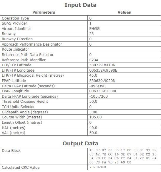
See EHGG AD 2.22 for FAS data block
|
|
EHGG AD 2.20 LOCAL AERODROME REGULATIONS
|
|
|
|
-
Monitoring the Eelde Tower channel is mandatory for all aircraft on the ground that have an engine running.
-
Touch-and-go's are not allowed for non-home-based traffic within 15 MIN before closing time.
|
|
|
-
Training flights are prohibited for jet aircraft and aircraft with a MTOM >= 6000 KG.
-
Training flights are prohibited during the following periods:
-
MON-SAT: before 0700 (0600) and after 2100 (2000).
-
SUN and HOL: before 0900 (0800) and after 1800 (1700).
-
IFR training flights outside operational hours Eelde Approach: PPR from ATC, TEL: +31 (0)50 309 9229.
-
Helicopter training flights not allowed (HEMS, police and military exempted).
|
3 TEST AND TECHNICAL FLIGHTS
|
Test or technical flights PPR from airport authority.
|
4 FORMATION TAKE-OFFS AND LANDINGS
|
Formation take-offs and landings are not allowed except with a pre-arranged operational agreement with ATC. Contact [email protected] for such an agreement.
|
5 REDUCED RUNWAY SEPARATION
|
-
Reduced runway separation may be applied between CAT 1 and 2 aircraft in accordance with AD 1.1 paragraph 5.3.
-
Minimum separation applicable for RWY 05 and RWY 23:
-
between a landing CAT 1 aircraft and a preceding CAT 1 or 2 aircraft: 600 M.
-
between a landing CAT 2 aircraft and a preceding CAT 1 or 2 aircraft: 1500 M.
-
between a departing CAT 1 aircraft and a preceding CAT 1 or 2 aircraft: 600 M.
-
between a departing CAT 2 aircraft and a preceding CAT 1 or 2 aircraft: 1500 M.
|
|
|
Handling is compulsory for all visiting ACFT MTOM >= 3000 KG, for details see EHGG AD 2.23.
|
|
|
The use of auxiliary power units (APU) and ground power units (GPU) is strictly controlled by airport authority at all aircraft stands. Flight crew are urgently requested to limit use of the APU as much as possible to reduce environmental and noise burden.
The APU should be shut down as soon as practicable following actual in block time (AIBT), but not later than 5 MIN after parking brakes set, and not restarted until 5 MIN prior to estimated off block time (EOBT) in order to start the engines.
Exceptions:
-
When it is necessary to use the APU to ensure safety on board (flight crew responsibility). Report to Airport Authority office as soon as practicable, TEL: +31 50 309 7014.
-
When the outside temperature is below 0°C or above +20°C (according to METAR).
-
When it is necessary to use an APU to diagnose and/or rectify aircraft faults (for technical/maintenance reasons). Prior permission required from the Airport Authority office, TEL: +31 50 309 7014.
|
8 USE OF TWY B (NORTH OF W1)
|
Usage of TWY B north of W1 limited: PPR by airport authority for all non-based jet aircraft, turboprop aircraft and helicopters.
|
9 USE OF ENGINE RUN-UP AREA
|
A public engine test and compass swing platform is available alongside TWY A, opposite the entry to the J-apron. The platform is intended for fixed wing non-turbine propellor aircraft with a MAX outer main gear wheel span of 4.5 M and a MAX wingspan of 15 M. Usage of this run-up area is possible MON-FRI 0600-1800 (MON-FRI 0500-1700) and requires PPR by the airport authority.
|
|
|
The area on TWY A, where the RFFS service road from J-apron to the runway intersects, should remain clear of aircraft as much as practicable.
|
11 ENVIRONMENTAL BURDEN REDUCTION DURING TAXI
|
In order to reduce the environmental burden:
-
after landing, all arriving aircraft shall switch off as many engines as possible before taxiing to the aircraft stand;
-
all departing aircraft shall use as few engines as possible whilst taxiing to the runway.
Reduced engine taxiing should only be executed when allowed in accordance with company standard operating procedures (SOP) and when deemed safe by the crew.
|
EHGG AD 2.21 NOISE ABATEMENT PROCEDURES
|
|
|
|
EHGG AD 2.22 FLIGHT PROCEDURES
|
|
1 INSTRUMENT DEPARTURE PROCEDURES
|
|
|
The instrument departure procedures are based on ICAO Annex 2 and on ICAO Documents 4444-ATM/501 (PANS-ATM), 7030 (SUPPS) and 8168-OPS/611 (PANS-OPS).
Note:
in the Eelde TMA VFR flights without ATC clearance are permitted. For instrument training procedures see EHGG AD 2.22 paragraph 4.
Note:
to avoid noise disturbances pilots shall adhere to the IFR departure procedures as depicted.
|
1.2 Instrument departure procedures
|
1.2.1 Start-up permission
|
Pilots of aircraft must have obtained permission for start-up from ATC before starting their engines and when applicable report a cross-bleed start. A request for start-up shall be made to Eelde Delivery after all preparations for departure have been made (doors closed etc.) and shall include:
-
aircraft identification (e.g. PH-SPY).
-
position (e.g. in front of terminal).
-
ATIS information (e.g. information S).
-
flight rules (e.g. IFR).
-
destination (e.g. Amsterdam).
-
request start-up.
Due to the short flying time to the FIR boundary, pilots of aircraft departing direction Germany/Denmark may request start-up permission before all preparations have been made, indicating the time at which they will be ready to start engines: "......destination.....ready to start engines at......".
Permission for start-up will either be issued immediately or at a specified time. The pilot shall be able to comply with start-up and taxi permission, since ATC planning of outbound traffic (involving en-route clearance and co-ordination with adjacent ACCs) is based on the start-up time. Any delay in start-up or taxiing shall be reported to ATC immediately.
In case of indefinite delay the probable duration of the delay will be given.
During the hours of the ATIS broadcast, no MET information will be issued to departing aircraft except RVR (see EHGG AD 2.18).
|
|
|
|
|
The en-route clearance will be issued after start-up clearance has been given by Eelde Delivery. An en-route clearance contains:
-
Clearance limit: airport of destination.
-
Standard instrument departure (SID).
-
Level instructions if applicable.
-
SSR code.
-
Departure instructions if applicable.
-
CTOT if applicable.
Example of an en-route clearance: "PHCTG cleared to Paris, PAM 4C departure, FL 070, squawk 2136, slot 25".
|
1.2.2.2 Standard instrument departures
|
The instrument departure procedures are laid down in standard instrument departures (SIDs). SIDs are designated in accordance with ICAO Annex 11. SID designation is composed of the following elements:
-
a basic indicator, i.e. a significant point.
-
a validity indicator, i.e. a number from 1 to 9 indicating the valid version of a specific SID.
-
a route indicator, i.e. a letter representing the runway where the SID begins.
SIDs are published for RWYs 05 and 23.
|
1.2.2.3 Departure instructions (paragraph 1.2.2.1 item d.)
|
Instructions containing deviations from the standard instrument departure may be added to the en-route or take-off clearance. These instructions may comprise an opposite turn after take-off, maintaining a specified heading or temporary altitude restrictions; they amend the relevant part of the SID only.
|
1.2.2.4 General instructions
|
-
Climb as rapidly as practicable to at least 2000 FT AMSL.
-
VOR radial interception angle: in principle 45°. If the indicated angle exceeds 45° initiate turn in due time in order not to overshoot the radial.
|
|
|
Aircraft shall request taxi clearance on the Tower frequency (see EHGG AD 2.18).
|
1.3 Communication failure
|
For the general procedures for IFR flights, see ENR 1.3 paragraph "Communication Failure".
Additionally, for departing flights, the following communication failure procedure applies:
- If a clearance to climb or re-routing instructions has not been given, comply with the route and altitude limitations detailed in the allocated standard instrument departure procedure or the departure instructions provided at take-off until the last waypoint has been reached.
|
|
|
|
|
-
Transition altitude: 3000 FT AMSL.
-
SIDs are based on an average climb rate of 2000 FT/min.
-
SIDs have to be considered as minimum noise routings.
-
Turn radii based on a 25° bank angle.
-
Radial interception angle: 45°.
-
MAX 250 KIAS below FL 100 unless otherwise instructed.
-
Additional departure instructions: especially propeller-driven aircraft can expect additional departure instructions. These instructions may be added to the en-route or take-off clearance and may comprise a specific heading or temporary altitude restriction. Such additives amend the relevant part of the SID only.
-
RNAV:
The Netherlands encourages the use of RNAV routes stored in a pre-programmed navigation database on board of aircraft. Although there may be differences between the RNAV and conventional description of a route (vertically: turn altitudes and/or laterally: turn anticipation effects), the resulting flight paths are considered identical by ATC. Therefore, flying the route using the RNAV coding from the navigation database will not result in route violations.
Furthermore:
-
Connect FMS as early as possible.
-
Turn anticipation is mandatory for all waypoints except those which are underlined, these waypoints shall be overflown.
-
The navigation aid (e.g. VOR) mentioned in the column "Expected path terminator" is for selection of MAG station declination only.
|
|
|
-
ENKOS departure only available for DEST EHRD.
-
NOVEN departure only available for DEST EHAM and intending to operate above FL 070.
-
ROLDU departure only available for DEST EHLE.
-
RUMER departure only available for flights operating MAX FL 095 to DEST EHEH, EHBD and EHBK.
-
TEBRO departure only available for DEST EDDL, EDLN and EDLV.
-
RNAV 1 required.
-
Initial turn: climb to 500 FT AMSL before turning, due to obstacles.
|
1.4.3 Continuous routings for SIDs with crossing conditions on ATS routes as applicable
|
Note:
REF EHGG AD 2.22 paragraph 1.2.2 "En-route clearance"-: if not able to comply with the crossing conditions prescribed in the SIDs, inform Eelde Delivery before departure.
Note: a
ircraft may only continue to climb above FL 060 or FL 070 after an ATC clearance has been received.
|
|
NAPRO Departures
|
|
Z739
|
If the requested flight level is a level above FL 245, cross AMOSU at or above FL 250. |
|
|
|
|
|
DOBAK 2C
[DOBA2C]
|
See paragraph 1.4.2 specific remark: 7.
After departure climb to FL 060. MNM required climb gradient 4.0% to FL 060 due to ATC restrictions.
|
|
Serial number
|
Path descriptor
|
WPT IDENT
|
Fly-over
|
Course/Track
°MAG / (°T)
|
Recom. navaid
|
DIST (NM)
|
Turn
|
Altitude (FT / FL)
|
Speed
(KIAS)
|
VPA (°) / TCH (FT)
|
NAV
specification
|
|
001
|
CF |
EEL |
N |
047 / (049.5) |
EEL |
- |
- |
- |
- |
- |
RNAV 1 |
|
002
|
TF |
DOBAK |
N |
078 / (081.3) |
- |
20.1 |
- |
+ FL 060 |
- |
- |
RNAV 1 |
Conventional
description
|
Lateral: Proceed to EEL VOR. Over EEL VOR intercept EEL 078 to DOBAK. |
|
Vertical: Cross 20.1 EEL at or above FL 060.
|
ENKOS 4C
[ENKO4C]
|
See paragraph 1.4.2 specific remark: 1, 6, 7.
After departure climb to FL 070.
|
|
Serial number
|
Path descriptor
|
WPT IDENT
|
Fly-over
|
Course/Track
°MAG / (°T)
|
Recom. navaid
|
DIST (NM)
|
Turn
|
Altitude (FT / FL)
|
Speed
(KIAS)
|
VPA (°) / TCH (FT)
|
NAV
specification
|
|
001
|
CF |
EEL |
N |
047 / (049.5) |
EEL |
- |
- |
- |
- |
- |
RNAV 1 |
|
002
|
TF |
GG516 |
N |
154 / (157.2) |
- |
11.6 |
- |
- |
- |
- |
RNAV 1 |
|
003
|
TF |
GG527 |
N |
260 / (262.7) |
- |
12.7 |
- |
- |
- |
- |
RNAV 1 |
|
004
|
TF |
OSTIR |
N |
244 / (247.2) |
- |
8.9 |
- |
+ FL 070 |
- |
- |
RNAV 1 |
|
005
|
TF |
ENKOS |
N |
247 / (249.7) |
- |
38.0 |
- |
- |
- |
- |
RNAV 1 |
NAPRO 3C
[NAPR3C]
|
See paragraph 1.4.2 specific remark: 6, 7.
After departure climb to FL 070.
|
|
Serial number
|
Path descriptor
|
WPT IDENT
|
Fly-over
|
Course/Track
°MAG / (°T)
|
Recom. navaid
|
DIST (NM)
|
Turn
|
Altitude (FT / FL)
|
Speed
(KIAS)
|
VPA (°) / TCH (FT)
|
NAV
specification
|
|
001
|
CF |
EEL |
N |
047 / (049.5) |
EEL |
- |
- |
- |
- |
- |
RNAV 1 |
|
002
|
TF |
GG516 |
N |
154 / (157.2) |
- |
11.6 |
- |
- |
- |
- |
RNAV 1 |
|
003
|
TF |
GG527 |
N |
260 / (262.7) |
- |
12.7 |
- |
- |
- |
- |
RNAV 1 |
|
004
|
TF |
VEROR |
N |
210 / (213.1) |
- |
4.1 |
- |
+ FL 070 |
- |
- |
RNAV 1 |
|
005
|
TF |
GG521 |
N |
210 / (213.0) |
- |
8.4 |
- |
- |
- |
- |
RNAV 1 |
|
006
|
TF |
GG522 |
N |
178 / (180.4) |
- |
24.2 |
- |
+ FL 110 |
- |
- |
RNAV 1 |
|
007
|
TF |
TENLI |
N |
178 / (180.4) |
- |
8.1 |
- |
- |
- |
- |
RNAV 1 |
|
008
|
TF |
NAPRO |
N |
194 / (196.9) |
- |
24.5 |
- |
- |
- |
- |
RNAV 1 |
NOVEN 3C
[NOVE3C]
|
See paragraph 1.4.2 specific remark: 2, 6, 7.
After departure climb to FL 070.
|
|
Serial number
|
Path descriptor
|
WPT IDENT
|
Fly-over
|
Course/Track
°MAG / (°T)
|
Recom. navaid
|
DIST (NM)
|
Turn
|
Altitude (FT / FL)
|
Speed
(KIAS)
|
VPA (°) / TCH (FT)
|
NAV
specification
|
|
001
|
CF |
EEL |
N |
047 / (049.5) |
EEL |
- |
- |
- |
- |
- |
RNAV 1 |
|
002
|
TF |
GG516 |
N |
154 / (157.2) |
- |
11.6 |
- |
- |
- |
- |
RNAV 1 |
|
003
|
TF |
GG527 |
N |
260 / (262.7) |
- |
12.7 |
- |
- |
- |
- |
RNAV 1 |
|
004
|
TF |
OSTIR |
N |
244 / (247.2) |
- |
8.9 |
- |
+ FL 070 |
- |
- |
RNAV 1 |
|
005
|
TF |
NOVEN |
N |
223 / (225.6) |
- |
16.4 |
- |
- |
- |
- |
RNAV 1 |
|
006
|
TF |
ARTIP |
N |
223 / (225.4) |
- |
17.0 |
- |
- |
- |
- |
RNAV 1 |
OLWOF 1C
[OLWO1C]
|
See paragraph 1.4.2 specific remark: 6, 7.
After departure climb to FL 060. MNM required climb gradient 4.3% to FL 060 due to ATC restrictions.
|
|
Serial number
|
Path descriptor
|
WPT IDENT
|
Fly-over
|
Course/Track
°MAG / (°T)
|
Recom. navaid
|
DIST (NM)
|
Turn
|
Altitude (FT / FL)
|
Speed
(KIAS)
|
VPA (°) / TCH (FT)
|
NAV
specification
|
|
001
|
CF |
EEL |
N |
047 / (049.5) |
EEL |
- |
- |
- |
- |
- |
RNAV 1 |
|
002
|
TF |
OLWOF |
N |
033 / (035.7) |
- |
17.4 |
- |
+ FL 060 |
- |
- |
RNAV 1 |
PAM 4C
[PAM4C]
|
See paragraph 1.4.2 specific remark: 6, 7.
After departure climb to FL 070.
|
|
Serial number
|
Path descriptor
|
WPT IDENT
|
Fly-over
|
Course/Track
°MAG / (°T)
|
Recom. navaid
|
DIST (NM)
|
Turn
|
Altitude (FT / FL)
|
Speed
(KIAS)
|
VPA (°) / TCH (FT)
|
NAV
specification
|
|
001
|
CF |
EEL |
N |
047 / (049.5) |
EEL |
- |
- |
- |
- |
- |
RNAV 1 |
|
002
|
TF |
GG516 |
N |
154 / (157.2) |
- |
11.6 |
- |
- |
- |
- |
RNAV 1 |
|
003
|
TF |
GG527 |
N |
260 / (262.7) |
- |
12.7 |
- |
- |
- |
- |
RNAV 1 |
|
004
|
TF |
OSTIR |
N |
244 / (247.2) |
- |
8.9 |
- |
+ FL 070 |
- |
- |
RNAV 1 |
|
005
|
TF |
GG528 |
N |
244 / (247.0) |
- |
4.8 |
- |
- |
- |
- |
RNAV 1 |
|
006
|
TF |
PAM |
N |
226 / (229.2) |
- |
48.8 |
- |
- |
- |
- |
RNAV 1 |
ROLDU 4C
[ROLD4C]
|
See paragraph 1.4.2 specific remark: 3, 6, 7.
After departure climb to maintain FL 050.
|
|
Serial number
|
Path descriptor
|
WPT IDENT
|
Fly-over
|
Course/Track
°MAG / (°T)
|
Recom. navaid
|
DIST (NM)
|
Turn
|
Altitude (FT / FL)
|
Speed
(KIAS)
|
VPA (°) / TCH (FT)
|
NAV
specification
|
|
001
|
CF |
EEL |
N |
047 / (049.5) |
EEL |
- |
- |
- |
- |
- |
RNAV 1 |
|
002
|
TF |
GG516 |
N |
154 / (157.2) |
- |
11.6 |
- |
- |
- |
- |
RNAV 1 |
|
003
|
TF |
GG527 |
N |
260 / (262.7) |
- |
12.7 |
- |
- |
- |
- |
RNAV 1 |
|
004
|
TF |
OSTIR |
N |
244 / (247.2) |
- |
8.9 |
- |
- |
- |
- |
RNAV 1 |
|
005
|
TF |
ROLDU
|
N |
223 / (225.6) |
- |
1.0 |
- |
@ FL 050 |
- |
- |
RNAV 1 |
RUMER 4C
[RUME4C]
|
See paragraph 1.4.2 specific remark: 4, 6, 7.
After departure climb to FL 070.
|
|
Serial number
|
Path descriptor
|
WPT IDENT
|
Fly-over
|
Course/Track
°MAG / (°T)
|
Recom. navaid
|
DIST (NM)
|
Turn
|
Altitude (FT / FL)
|
Speed
(KIAS)
|
VPA (°) / TCH (FT)
|
NAV
specification
|
|
001
|
CF |
EEL |
N |
047 / (049.5) |
EEL |
- |
- |
- |
- |
- |
RNAV 1 |
|
002
|
TF |
GG516 |
N |
154 / (157.2) |
- |
11.6 |
- |
- |
- |
- |
RNAV 1 |
|
003
|
TF |
GG527 |
N |
260 / (262.7) |
- |
12.7 |
- |
- |
- |
- |
RNAV 1 |
|
004
|
TF |
VEROR |
N |
210 / (213.1) |
- |
4.1 |
- |
+ FL 070 |
- |
- |
RNAV 1 |
|
005
|
TF |
GG521
|
N |
210 / (213.0) |
- |
8.4 |
- |
- |
- |
- |
RNAV 1 |
|
006
|
TF |
TENLI |
N |
178 / (180.4) |
- |
32.3 |
- |
- |
- |
- |
RNAV 1 |
|
007
|
TF |
NIHOF |
N |
178 / (180.4) |
- |
14.2 |
- |
- |
- |
- |
RNAV 1 |
|
008
|
TF |
BASGU |
N |
246 / (248.6) |
- |
15.9 |
- |
- |
- |
- |
RNAV 1 |
|
009
|
TF |
RUMER |
N |
173 / (175.8) |
- |
17.6 |
- |
- |
- |
- |
RNAV 1 |
SONEB 4C
[SONE4C]
|
See paragraph 1.4.2 specific remark: 6, 7.
After departure climb to FL 070.
|
|
Serial number
|
Path descriptor
|
WPT IDENT
|
Fly-over
|
Course/Track
°MAG / (°T)
|
Recom. navaid
|
DIST (NM)
|
Turn
|
Altitude (FT / FL)
|
Speed
(KIAS)
|
VPA (°) / TCH (FT)
|
NAV
specification
|
|
001
|
CF |
EEL |
N |
047 / (049.5) |
EEL |
- |
- |
- |
- |
- |
RNAV 1 |
|
002
|
TF |
GG516 |
N |
154 / (157.2) |
- |
11.6 |
- |
- |
- |
- |
RNAV 1 |
|
003
|
TF |
GG527 |
N |
260 / (262.7) |
- |
12.7 |
- |
- |
- |
- |
RNAV 1 |
|
004
|
TF |
VEROR |
N |
210 / (213.1) |
- |
4.1 |
- |
+ FL 070 |
- |
- |
RNAV 1 |
|
005
|
TF |
GG521
|
N |
210 / (213.0) |
- |
8.4 |
- |
- |
- |
- |
RNAV 1 |
|
006
|
TF |
TENLI |
N |
178 / (180.4) |
- |
32.3 |
- |
- |
- |
- |
RNAV 1 |
|
007
|
TF |
SONEB |
N |
122 / (125.0) |
- |
23.3 |
- |
- |
- |
- |
RNAV 1 |
SPY 4C
[SPY4C]
|
See paragraph 1.4.2 specific remark: 6, 7.
After departure climb to FL 070.
|
|
Serial number
|
Path descriptor
|
WPT IDENT
|
Fly-over
|
Course/Track
°MAG / (°T)
|
Recom. navaid
|
DIST (NM)
|
Turn
|
Altitude (FT / FL)
|
Speed
(KIAS)
|
VPA (°) / TCH (FT)
|
NAV
specification
|
|
001
|
CF |
EEL |
N |
047 / (049.5) |
EEL |
- |
- |
- |
- |
- |
RNAV 1 |
|
002
|
TF |
GG516 |
N |
154 / (157.2) |
- |
11.6 |
- |
- |
- |
- |
RNAV 1 |
|
003
|
TF |
GG527 |
N |
260 / (262.7) |
- |
12.7 |
- |
- |
- |
- |
RNAV 1 |
|
004
|
TF |
OSTIR |
N |
244 / (247.2) |
- |
8.9 |
- |
+ FL 070 |
- |
- |
RNAV 1 |
|
005
|
TF |
SPY |
N |
244 / (247.0) |
- |
54.3 |
- |
- |
- |
- |
RNAV 1 |
TEBRO 4C
[TEBR4C]
|
See paragraph 1.4.2 specific remark: 5, 6, 7.
After departure climb to FL 070.
|
|
Serial number
|
Path descriptor
|
WPT IDENT
|
Fly-over
|
Course/Track
°MAG / (°T)
|
Recom. navaid
|
DIST (NM)
|
Turn
|
Altitude (FT / FL)
|
Speed
(KIAS)
|
VPA (°) / TCH (FT)
|
NAV
specification
|
|
001
|
CF |
EEL |
N |
047 / (049.5) |
EEL |
- |
- |
- |
- |
- |
RNAV 1 |
|
002
|
TF |
GG516 |
N |
154 / (157.2) |
- |
11.6 |
- |
- |
- |
- |
RNAV 1 |
|
003
|
TF |
GG527 |
N |
260 / (262.7) |
- |
12.7 |
- |
- |
- |
- |
RNAV 1 |
|
004
|
TF |
VEROR |
N |
210 / (213.1) |
- |
4.1 |
- |
+ FL 070 |
- |
- |
RNAV 1 |
|
005
|
TF |
GG521
|
N |
210 / (213.0) |
- |
8.4 |
- |
- |
- |
- |
RNAV 1 |
|
006
|
TF |
TENLI |
N |
178 / (180.4) |
- |
32.3 |
- |
- |
- |
- |
RNAV 1 |
|
007
|
TF |
TEBRO |
N |
146 / (149.3) |
- |
24.6 |
- |
- |
- |
- |
RNAV 1 |
TEMLU 2C
[TEML2C]
|
See paragraph 1.4.2 specific remark: 6, 7.
After departure climb to FL 060. MNM required climb gradient 4.0% to FL 060 due to ATC restrictions.
|
|
Serial number
|
Path descriptor
|
WPT IDENT
|
Fly-over
|
Course/Track
°MAG / (°T)
|
Recom. navaid
|
DIST (NM)
|
Turn
|
Altitude (FT / FL)
|
Speed
(KIAS)
|
VPA (°) / TCH (FT)
|
NAV
specification
|
|
001
|
CF |
EEL |
N |
047 / (049.5) |
EEL |
- |
- |
- |
- |
- |
RNAV 1 |
|
002
|
TF |
TEMLU |
N |
018 / (020.7) |
- |
20.0 |
- |
+ FL 060 |
- |
- |
RNAV 1 |
|
|
|
|
|
DOBAK 3D
[DOBA3D]
|
See paragraph 1.4.2 specific remark: 7.
After departure climb to FL 060.
|
|
Serial number
|
Path descriptor
|
WPT IDENT
|
Fly-over
|
Course/Track
°MAG / (°T)
|
Recom. navaid
|
DIST (NM)
|
Turn
|
Altitude (FT / FL)
|
Speed
(KIAS)
|
VPA (°) / TCH (FT)
|
NAV
specification
|
|
001
|
CF |
GG529 |
N |
229 / (231.8) |
EEL |
- |
- |
- |
- |
- |
RNAV 1 |
|
002
|
TF |
GG533 |
N |
131 / (134.4) |
- |
8.0 |
- |
- |
- |
- |
RNAV 1 |
|
003
|
TF |
GG536 |
N |
034 / (037.0) |
- |
14.6 |
- |
- |
- |
- |
RNAV 1 |
|
004
|
TF |
DOBAK |
N |
078 / (081.5) |
- |
11.2 |
- |
+ FL 060 |
- |
- |
RNAV 1 |
Conventional
description
|
Lateral: Track 229° MAG. At 6.2 EEL turn left to 131° MAG. At EEL 188 turn left to 034° MAG to intercept EEL 078 to DOBAK. |
|
Vertical: Cross 20.1 EEL at or above FL 060.
|
ENKOS 2D
[ENKO2D]
|
See paragraph 1.4.2 specific remark: 1, 6, 7.
After departure climb to FL 070. MNM required climb gradient 7.5% to FL 070 due to ATC restrictions.
|
|
Serial number
|
Path descriptor
|
WPT IDENT
|
Fly-over
|
Course/Track
°MAG / (°T)
|
Recom. navaid
|
DIST (NM)
|
Turn
|
Altitude (FT / FL)
|
Speed
(KIAS)
|
VPA (°) / TCH (FT)
|
NAV
specification
|
|
001
|
CF |
GG529 |
N |
229 / (231.8) |
EEL |
- |
- |
- |
- |
- |
RNAV 1 |
|
002
|
TF |
GG530 |
N |
258 / (261.1) |
- |
3.8 |
- |
- |
- |
- |
RNAV 1 |
|
003
|
TF |
DIVPA |
N |
238 / (240.9) |
- |
9.2 |
- |
+ FL 070 |
- |
- |
RNAV 1 |
|
004
|
TF |
ENKOS |
N |
238 / (240.7) |
- |
39.4 |
- |
- |
- |
- |
RNAV 1 |
NAPRO 2D
[NAPR2D]
|
See paragraph 1.4.2 specific remark: 6, 7.
After departure climb to FL 070. MNM required climb gradient 8.0% to FL 070 due to ATC restrictions
|
|
Serial number
|
Path descriptor
|
WPT IDENT
|
Fly-over
|
Course/Track
°MAG / (°T)
|
Recom. navaid
|
DIST (NM)
|
Turn
|
Altitude (FT / FL)
|
Speed
(KIAS)
|
VPA (°) / TCH (FT)
|
NAV
specification
|
|
001
|
CF |
GG529 |
N |
229 / (231.8) |
EEL |
- |
- |
- |
- |
- |
RNAV 1 |
|
002
|
TF |
GG527 |
N |
194 / (197.2) |
- |
8.1 |
- |
- |
- |
- |
RNAV 1 |
|
003
|
TF |
VEROR |
N |
210 / (213.1) |
- |
4.1 |
- |
+ FL 070 |
- |
- |
RNAV 1 |
|
004
|
TF |
GG521 |
N |
210 / (213.0) |
- |
8.4 |
- |
- |
- |
- |
RNAV 1 |
|
005
|
TF |
GG522 |
N |
178 / (180.4) |
- |
24.2 |
- |
+ FL 110 |
- |
- |
RNAV 1 |
|
006
|
TF |
TENLI |
N |
178 / (180.4) |
- |
8.1 |
- |
- |
- |
- |
RNAV 1 |
|
007
|
TF |
NAPRO |
N |
194 / (196.9) |
- |
24.5 |
- |
- |
- |
- |
RNAV 1 |
NOVEN 2D
[NOVE2D]
|
See paragraph 1.4.2 specific remark: 2, 6, 7.
After departure climb to FL 070. MNM required climb gradient 6.5% to FL 070 due to ATC restrictions.
|
|
Serial number
|
Path descriptor
|
WPT IDENT
|
Fly-over
|
Course/Track
°MAG / (°T)
|
Recom. navaid
|
DIST (NM)
|
Turn
|
Altitude (FT / FL)
|
Speed
(KIAS)
|
VPA (°) / TCH (FT)
|
NAV
specification
|
|
001
|
CF |
GG529 |
N |
229 / (231.8) |
EEL |
- |
- |
- |
- |
- |
RNAV 1 |
|
002
|
TF |
GG532 |
N |
211 / (213.8) |
- |
3.0 |
- |
- |
- |
- |
RNAV 1 |
|
003
|
TF |
OSTIR |
N |
223 / (225.8) |
- |
12.4 |
- |
+ FL 070 |
- |
- |
RNAV 1 |
|
004
|
TF |
NOVEN |
N |
223 / (225.6) |
- |
16.4 |
- |
- |
- |
- |
RNAV 1 |
|
005
|
TF |
ARTIP |
N |
223 / (225.4) |
- |
17.0 |
- |
- |
- |
- |
RNAV 1 |
OLWOF 1D
[OLWO1D]
|
See paragraph 1.4.2 specific remark: 6, 7.
After departure climb to FL 060.
|
|
Serial number
|
Path descriptor
|
WPT IDENT
|
Fly-over
|
Course/Track
°MAG / (°T)
|
Recom. navaid
|
DIST (NM)
|
Turn
|
Altitude (FT / FL)
|
Speed
(KIAS)
|
VPA (°) / TCH (FT)
|
NAV
specification
|
|
001
|
CF |
GG529 |
N |
229 / (231.8) |
EEL |
- |
- |
- |
- |
- |
RNAV 1 |
|
002
|
TF |
GG533 |
N |
131 / (134.4) |
- |
8.0 |
- |
- |
- |
- |
RNAV 1 |
|
003
|
TF |
GG535 |
N |
034 / (037.0) |
- |
6.7 |
- |
- |
- |
- |
RNAV 1 |
|
004
|
TF |
EEL |
N |
318 / (320.6) |
- |
6.4 |
- |
- |
- |
- |
RNAV 1 |
|
005
|
TF |
OLWOF |
N |
033 / (035.7) |
- |
17.4 |
- |
+ FL 060 |
- |
- |
RNAV 1 |
PAM 3D
[PAM3D]
|
See paragraph 1.4.2 specific remark: 6, 7.
After departure climb to FL 070. MNM required climb gradient 6.5% to FL 070 due to ATC restrictions.
|
|
Serial number
|
Path descriptor
|
WPT IDENT
|
Fly-over
|
Course/Track
°MAG / (°T)
|
Recom. navaid
|
DIST (NM)
|
Turn
|
Altitude (FT / FL)
|
Speed
(KIAS)
|
VPA (°) / TCH (FT)
|
NAV
specification
|
|
001
|
CF |
GG529 |
N |
229 / (231.8) |
EEL |
- |
- |
- |
- |
- |
RNAV 1 |
|
002
|
TF |
GG532 |
N |
211 / (213.8) |
- |
3.0 |
- |
- |
- |
- |
RNAV 1 |
|
003
|
TF |
OSTIR |
N |
223 / (225.8) |
- |
12.4 |
- |
+ FL 070 |
- |
- |
RNAV 1 |
|
004
|
TF |
GG528 |
N |
244 / (247.0) |
- |
4.8 |
- |
- |
- |
- |
RNAV 1 |
|
005
|
TF |
PAM |
N |
226 / (229.2) |
- |
48.8 |
- |
- |
- |
- |
RNAV 1 |
ROLDU 2D
[ROLD2D]
|
See paragraph 1.4.2 specific remark: 3, 6, 7.
After departure climb to maintain FL 050. MNM required climb gradient 4.4% to FL 050 due to ATC restrictions.
|
|
Serial number
|
Path descriptor
|
WPT IDENT
|
Fly-over
|
Course/Track
°MAG / (°T)
|
Recom. navaid
|
DIST (NM)
|
Turn
|
Altitude (FT / FL)
|
Speed
(KIAS)
|
VPA (°) / TCH (FT)
|
NAV
specification
|
|
001
|
CF |
GG529 |
N |
229 / (231.8) |
EEL |
- |
- |
- |
- |
- |
RNAV 1 |
|
002
|
TF |
GG532 |
N |
211 / (213.8) |
- |
3.0 |
- |
- |
- |
- |
RNAV 1 |
|
003
|
TF |
OSTIR |
N |
223 / (225.8) |
- |
12.4 |
- |
- |
- |
- |
RNAV 1 |
|
004
|
TF |
ROLDU |
N |
223 / (225.6) |
- |
1.0 |
- |
@ FL 050 |
- |
- |
RNAV 1 |
RUMER 3D
[RUME3D]
|
See paragraph 1.4.2 specific remark: 4, 6, 7.
After departure climb to FL 070. MNM required climb gradient 8.0% to FL 070 due to ATC restrictions.
|
|
Serial number
|
Path descriptor
|
WPT IDENT
|
Fly-over
|
Course/Track
°MAG / (°T)
|
Recom. navaid
|
DIST (NM)
|
Turn
|
Altitude (FT / FL)
|
Speed
(KIAS)
|
VPA (°) / TCH (FT)
|
NAV
specification
|
|
001
|
CF |
GG529 |
N |
229 / (231.8) |
EEL |
- |
- |
- |
- |
- |
RNAV 1 |
|
002
|
TF |
GG527 |
N |
194 / (197.2) |
- |
8.1 |
- |
- |
- |
- |
RNAV 1 |
|
003
|
TF |
VEROR |
N |
210 / (213.1) |
- |
4.1 |
- |
+ FL 070 |
- |
- |
RNAV 1 |
|
004
|
TF |
GG521 |
N |
210 / (213.0) |
- |
8.4 |
|
- |
- |
- |
RNAV 1 |
|
005
|
TF |
TENLI |
N |
178 / (180.4) |
- |
32.3 |
- |
- |
- |
- |
RNAV 1 |
|
006
|
TF |
NIHOF |
N |
178 / (180.4) |
- |
14.2 |
- |
- |
- |
- |
RNAV 1 |
|
007
|
TF |
BASGU |
N |
246 / (248.6) |
- |
15.9 |
- |
- |
- |
- |
RNAV 1 |
|
008
|
TF |
RUMER |
N |
173 / (175.8) |
- |
17.6 |
- |
- |
- |
- |
RNAV 1 |
SONEB 3D
[SONE3D]
|
See paragraph 1.4.2 specific remark: 6, 7.
After departure climb to FL 070. MNM required climb gradient 8.0% to FL 070 due to ATC restrictions.
|
|
Serial number
|
Path descriptor
|
WPT IDENT
|
Fly-over
|
Course/Track
°MAG / (°T)
|
Recom. navaid
|
DIST (NM)
|
Turn
|
Altitude (FT / FL)
|
Speed
(KIAS)
|
VPA (°) / TCH (FT)
|
NAV
specification
|
|
001
|
CF |
GG529 |
N |
229 / (231.8) |
EEL |
- |
- |
- |
- |
- |
RNAV 1 |
|
002
|
TF |
GG527 |
N |
194 / (197.2) |
- |
8.1 |
- |
- |
- |
- |
RNAV 1 |
|
003
|
TF |
VEROR |
N |
210 / (213.1) |
- |
4.1 |
- |
+ FL 070 |
- |
- |
RNAV 1 |
|
004
|
TF |
GG521 |
N |
210 / (213.0) |
- |
8.4 |
|
- |
- |
- |
RNAV 1 |
|
005
|
TF |
TENLI |
N |
178 / (180.4) |
- |
32.3 |
- |
- |
- |
- |
RNAV 1 |
|
006
|
TF |
SONEB |
N |
122 / (125.0) |
- |
23.3 |
- |
- |
- |
- |
RNAV 1 |
SPY 2D
[SPY2D]
|
See paragraph 1.4.2 specific remark: 6, 7.
After departure climb to FL 070. MNM required climb gradient 7.5% to FL 070 due to ATC restrictions.
|
|
Serial number
|
Path descriptor
|
WPT IDENT
|
Fly-over
|
Course/Track
°MAG / (°T)
|
Recom. navaid
|
DIST (NM)
|
Turn
|
Altitude (FT / FL)
|
Speed
(KIAS)
|
VPA (°) / TCH (FT)
|
NAV
specification
|
|
001
|
CF |
GG529 |
N |
229 / (231.8) |
EEL |
- |
- |
- |
- |
- |
RNAV 1 |
|
002
|
TF |
GG530 |
N |
258 / (261.1) |
- |
3.8 |
- |
- |
- |
- |
RNAV 1 |
|
003
|
TF |
DIVPA |
N |
238 / (240.9) |
- |
9.2 |
- |
+ FL 070 |
- |
- |
RNAV 1 |
|
004
|
TF |
SPY |
N |
238 / (240.7) |
- |
55.9 |
|
- |
- |
- |
RNAV 1 |
TEBRO 3D
[TEBR3D]
|
See paragraph 1.4.2 specific remark: 5, 6, 7.
After departure climb to FL 070. MNM required climb gradient 8.0% to FL 070 due to ATC restrictions.
|
|
Serial number
|
Path descriptor
|
WPT IDENT
|
Fly-over
|
Course/Track
°MAG / (°T)
|
Recom. navaid
|
DIST (NM)
|
Turn
|
Altitude (FT / FL)
|
Speed
(KIAS)
|
VPA (°) / TCH (FT)
|
NAV
specification
|
|
001
|
CF |
GG529 |
N |
229 / (231.8) |
EEL |
- |
- |
- |
- |
- |
RNAV 1 |
|
002
|
TF |
GG527 |
N |
194 / (197.2) |
- |
8.1 |
- |
- |
- |
- |
RNAV 1 |
|
003
|
TF |
VEROR |
N |
210 / (213.1) |
- |
4.1 |
- |
+ FL 070 |
- |
- |
RNAV 1 |
|
004
|
TF |
GG521 |
N |
210 / (213.0) |
- |
8.4 |
- |
- |
- |
- |
RNAV 1 |
|
005
|
TF |
TENLI |
N |
178 / (180.4) |
- |
32.3 |
- |
- |
|
|
RNAV 1 |
|
006
|
TF |
TEBRO |
N |
146 / (149.3) |
- |
24.6 |
- |
- |
- |
|
RNAV 1 |
TEMLU 3D
[TEML3D]
|
See paragraph 1.4.2 specific remark: 6, 7.
After departure climb to FL 060.
|
|
Serial number
|
Path descriptor
|
WPT IDENT
|
Fly-over
|
Course/Track
°MAG / (°T)
|
Recom. navaid
|
DIST (NM)
|
Turn
|
Altitude (FT / FL)
|
Speed
(KIAS)
|
VPA (°) / TCH (FT)
|
NAV
specification
|
|
001
|
CF |
GG529 |
N |
229 / (231.8) |
EEL |
- |
- |
- |
- |
- |
RNAV 1 |
|
002
|
TF |
GG533 |
N |
131 / (134.4) |
- |
8.0 |
- |
- |
- |
- |
RNAV 1 |
|
003
|
TF |
GG535 |
N |
034 / (037.0) |
- |
6.7 |
- |
- |
- |
- |
RNAV 1 |
|
004
|
TF |
EEL |
N |
318 / (320.6) |
- |
6.4 |
- |
- |
- |
- |
RNAV 1 |
|
005
|
TF |
TEMLU |
N |
018 / (020.7) |
- |
20.0 |
- |
+ FL 060 |
|
|
RNAV 1 |
|
2 INSTRUMENT APPROACH PROCEDURES
|
|
|
The arrival, instrument approach and holding procedures are based on ICAO Annex 2 and on ICAO Documents 4444-ATM/501 (PANS-ATM), 7030 (SUPPS) and 8168-OPS/611 (PANS-OPS). During initial and intermediate approach to Eelde Airport radar services may be provided by Eelde APP.
Note:
in the Eelde TMA VFR flights without ATC clearance are permitted. For instrument training procedures see EHGG AD 2.22 paragraph 4.
Note:
to avoid noise disturbances pilots shall adhere to the IFR approach procedures as depicted.
|
|
|
|
|
At, or before, entering the Eelde TMA, an arrival clearance will be issued by Amsterdam ACC containing:
-
Standard arrival route
1) or direct route.
-
Main landing runway
2).
-
Level instructions (normally descent instructions).
-
Any other necessary instructions or information.
|
1)when cleared via a standard arrival route (STAR), the clearance limit is the initial approach fix (lAF).
2)issued by ATIS (see EHGG AD 2.18) or ATC.
|
2.2.2 Transfer from ACC to APP
|
Transfer to Eelde APP will normally take place when the flight is entering the Eelde TMA.
|
|
|
|
|
|
DOBAK 2G
|
RNAV 1 required. |
|
ARINC designator
|
Formal description
|
Abbreviated description
|
Expected path terminator
|
Fly-over
required
|
|
[DOBA2G]
|
DOBAK |
DOBAK |
IF |
N |
|
To HECTI
|
HECTI |
TF |
N |
|
GRONY 2G
|
RNAV 1 required. |
|
ARINC designator
|
Formal description
|
Abbreviated description
|
Expected path terminator
|
Fly-over
required
|
|
[GRON2G]
|
GRONY |
GRONY |
IF |
N |
|
To EEL
|
EEL |
TF |
N |
|
To HECTI
|
HECTI |
TF |
N |
|
KUBAT 2G
|
RNAV 1 required. |
|
ARINC designator
|
Formal description
|
Abbreviated description
|
Expected path terminator
|
Fly-over
required
|
|
[KUBA2G]
|
KUBAT |
KUBAT |
IF |
N |
|
To HECTI
|
HECTI |
TF |
N |
|
OLWOF 1G
|
RNAV 1 required. |
|
ARINC designator
|
Formal description
|
Abbreviated description
|
Expected path terminator
|
Fly-over
required
|
|
[OLWO1G]
|
OLWOF |
OLWOF |
IF |
N |
|
To HECTI
|
HECTI |
TF |
N |
|
OSTIR 2G
|
RNAV 1 required. |
|
ARINC designator
|
Formal description
|
Abbreviated description
|
Expected path terminator
|
Fly-over
required
|
|
[OSTI2G]
|
OSTIR |
OSTIR |
IF |
N |
|
To EEL
|
EEL |
TF |
N |
|
To HECTI
|
HECTI |
TF |
N |
|
RKN 2G
|
RNAV 1 required. |
|
ARINC designator
|
Formal description
|
Abbreviated description
|
Expected path terminator
|
Fly-over
required
|
|
[RKN2G]
|
RKN |
RKN |
IF |
N |
|
To GG522
|
GG522 |
TF |
N |
|
To GG521
|
GG521 |
TF |
N |
|
To VEROR
|
VEROR |
TF |
N |
|
To EEL
|
EEL |
TF |
N |
|
To HECTI
|
HECTI |
TF |
N |
|
TEMLU 2G
|
RNAV 1 required. |
|
ARINC designator
|
Formal description
|
Abbreviated description
|
Expected path terminator
|
Fly-over
required
|
|
[TEML2G]
|
TEMLU |
TEMLU |
IF |
N |
|
To HECTI
|
HECTI |
TF |
N |
|
TENLI 2G
|
RNAV 1 required. |
|
ARINC designator
|
Formal description
|
Abbreviated description
|
Expected path terminator
|
Fly-over
required
|
|
[TENL2G]
|
TENLI |
TENLI |
IF |
N |
|
To GG522
|
GG522 |
TF |
N |
|
To GG521
|
GG521 |
TF |
N |
|
To VEROR
|
VEROR |
TF |
N |
|
To EEL
|
EEL |
TF |
N |
|
To HECTI
|
HECTI |
TF |
N |
|
|
|
|
|
Procedure
IDENT
|
WPT
IDENT
|
Fly-over
required
|
Direction MAG
|
Time (MIN)
|
Turn direction
|
Altitude (FT / FL)
|
MAX Speed
(KIAS)
|
NAV specification
|
|
HECTI
|
HECTI |
Y |
231 |
1 |
R |
2000 |
220 |
RNAV 1 |
|
|
|
|
|
Holding and entry procedures and the calculations of the associated protected areas are in accordance with PANS-OPS Volume II, part 4. Since separation is based on the calculated areas, compliance with these in-flight procedures is essential.
|
2.3.2 Approach instructions
|
Approach instructions will contain as applicable:
-
Additional instructions with respect to clearance limit, route and level.
-
Approach procedure.
-
Runway in use
1).
-
EAT, if holding procedures are applied.
-
QNH.
-
Transition level
1).
-
MET information
1).
-
Runway condition
1).
1)during the hours of ATIS broadcast (see EHGG AD 2.18), item may be omitted as far as it is included in the ATIS broadcast.
|
2.3.3 RNAV to ILS approach procedure
|
An RNAV to ILS approach procedure can be initiated by ATC in order to reduce noise nuisance, fuel consumption, and to provide flexible and efficient ATC dispatch.
|
|
|
The RNAV to ILS approach procedure in the Eelde TMA is developed in accordance with ICAO PANS-OPS criteria with the following safeguards:
-
The RNAV section of the inbound route is situated above MSA/MFA/MVA.
-
The RNAV part is complete on entering the intermediate segment in which ILS-LOC interception takes place.
-
If radar service is available the operations will be radar monitored by ATC.
|
2.3.3.2 Clearances and constraints
|
On initiative of ATC, pilots may be instructed to fly an RNAV approach procedure preceding the ILS instrument approach to RWY 23.
-
This RNAV to ILS approach procedure starts at waypoint TOLKO.
-
After receiving a clearance for the RNAV to ILS approach procedure the pilot is free to optimise the descent and speed within the constraints as laid down in the procedure description, with the objective to establish a low noise continuous descent approach.
-
The clearance for the RNAV to ILS approach procedure includes clearance to execute the subsequent ILS instrument approach procedure.
Further details are published in paragraph 2.6.2 and on the chart IAC TOLKO 2G approach ILS RWY 23.
|
2.3.3.3 Aircraft requirements
|
For the use of the RNAV to ILS approach procedure the following requirements are applicable:
-
The aircraft must be equipped with an FMS comprising a pre-loaded navigation database and a navigation display.
-
The aircraft FMS must use GNSS as the primary navigation sensor.
-
The operator must be approved for RNAV 1 operations by their state of registry.
|
2.3.3.4 Non-RNAV equipped aircraft
|
Pilots of aircraft that are not equipped or approved for TMA RNAV procedures, i.e. not meeting the requirements in paragraph 2.3.3.3, shall inform ATC by use of the phrase "UNABLE (designator) APPROACH DUE RNAV TYPE" if instructed to fly an RNAV approach procedure. These aircraft will be guided by vectors or will be rerouted via conventional navigation aids.
|
2.4 Intermediate and final approach
|
2.4.1 Final approach procedures
|
Note:
an aircraft vectored to intercept final approach shall report to ATC when established on the final approach track (ICAO Doc 4444-ATM/501 (PANS-ATM) chapter 8.9.4.1).
|
|
|
In principle the final approach will be conducted on main landing RWY 23. An alternate runway can be offered in case of excessive crosswind or unserviceability of the ILS.
|
2.4.1.2 Instrument approaches
|
ILS approaches can be made to RWY 23 only. RNP approaches to LPV and LNAV minima are available for both RWY 05 and RWY 23. Instrument approaches to RWY 05 and RWY 23 can also be made with the assistance of VOR.
For the use of an RNP approach it is required that the operator holds an RNP APCH operations approval issued by their State of registry. The approval should be compliant with EASA CS-ACNS or equivalent.
|
|
|
To minimise noise nuisance, aircraft executing a visual approach shall intercept the final approach leg at an altitude of at least 1000 FT AMSL, unless residential areas can be avoided.
|
2.4.1.4 Circling approach
|
For each runway at Eelde Airport a circling approach may be allowed or offered. For OCA (OCH) see relevant instrument approach chart.
|
2.4.2 Missed approach procedure
|
|
|
All turns shall be the shortest turn and in case of a 180° turn that turn shall be to the left, unless otherwise specified below or instructed by ATC.
|
2.4.2.2 Missed approach procedure during instrument approach
|
See relevant instrument approach chart.
|
2.4.2.3 Missed approach procedure during visual approach
|
Turn to the intended landing runway, intercept the runway track MAG of that runway while:
-
When visual:
-
remain visual and inform ATC, or
-
When unable to remain visual:
-
climb to 2000 FT AMSL and inform ATC.
|
2.4.2.4 Missed approach while circling to land
|
Note: t
his procedure is different from ICAO Doc 8168 Volume I (PANS-OPS).
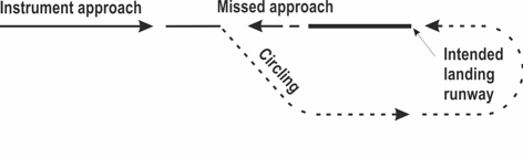
|
-
Inform ATC immediately.
-
Start climbing and complete the turn to the intended landing runway (see figure).
-
Intercept the MAG track of that runway while climbing to 2000 FT AMSL.
|
|
|
|
|
Note:
|
the indicated situation is applicable for an initial instrument approach to RWY 05. Circling approaches shall be executed south-east of the AD, unless otherwise instructed by ATC.
|
|
|
|
2.5 Communication failure
|
|
|
The pilot of an IFR flight shall follow the general procedures for IFR flights (see ENR 1.3 paragraph "Communication Failure"). Additionally, for arriving flights, the following communication failure procedures apply.
|
2.5.2 Inbound clearance not received
|
-
Proceed according the current flight plan route to the holding fix HECTI. Non-RNAV traffic proceed to HECTI via DCT EEL and EEL 051.
-
Maintain the last cleared and acknowledged flight level.
-
After arrival over HECTI, intercept the holding pattern.
-
Commence descent to 2000 FT AMSL at or as near as possible to the ETO over HECTI.
-
After reaching 2000 FT AMSL leave HECTI and carry out an instrument approach procedure to the most convenient runway (see relevant instrument approach chart).
|
2.5.3 Inbound clearance received
|
2.5.3.1 Traffic via standard arrival route, outside standard arrival route or vectored to final approach
|
-
Proceed according the current flight plan route to the holding fix HECTI or OMFAR, if specified in the inbound clearance. Non-RNAV traffic proceed to HECTI via DCT EEL and EEL 051 and OMFAR via DCT EEL and EEL 229.
-
Maintain the last cleared and acknowledged flight level.
-
After arrival over the fix, intercept the holding pattern.
-
Commence descent to 2000 FT AMSL at the EAT last received and acknowledged.
-
When no EAT has been received and acknowledged, commence descent to 2000 FT AMSL at or as near as possible to the ETO over holding fix.
-
After reaching 2000 FT AMSL leave the holding fix and carry out an instrument approach procedure to the appropriate runway (see relevant instrument approach chart).
|
2.5.3.2 Traffic inbound TOLKO or on RNAV to ILS approach
|
-
Traffic inbound TOLKO or with clearance for the RNAV approach via TOLKO, shall proceed to TOLKO and execute the RNAV to ILS approach procedure.
|
2.5.3.3 Traffic inbound AMREG, IDAKA, SIPLO, TUVOX, VEXAR, XOMBI or on RNP approach
|
Traffic inbound an IAF or IF, or with clearance for the RNP approach to RWY 05 or RWY 23, shall proceed to this IAF or IF and execute the RNP approach procedure in accordance with the applicable instrument approach chart (see chart IAC RNP RWY 05 or IAC RNP RWY 23).
|
2.5.4 Missed approach procedure in case of communication failure
|
|
|
All turns shall be the shortest turn and in case of a 180° turn that turn shall be to the left, unless otherwise specified below or instructed by ATC.
|
2.5.4.2 Missed approach procedure during instrument approach
|
See relevant instrument approach chart.
|
2.5.4.3 Missed approach procedure during visual approach
|
Turn to the intended landing runway, intercept the runway track MAG of that runway while:
-
When visual:
-
remain visual and execute another circuit for that runway, or
-
When unable to remain visual:
-
climb to 3000 FT AMSL;
-
in case a visual approach was made to RWY 05: when reaching 2000 FT AMSL turn left to intercept EEL 229 and proceed to OMFAR, or
-
in case a visual approach was made to RWY 23: when reaching 2000 FT AMSL turn right to EEL. After passing EEL proceed to HECTI via EEL 051, and
-
after arriving over the fix for the approach runway (OMFAR for RWY 05, HECTI for RWY 23) hold or descend to 2000 FT AMSL in an outbound turn, intercept final approach and execute the instrument approach procedure as depicted on the relevant approach chart.
|
2.5.4.4 Missed approach while circling to land
|
Note: t
his procedure is different from ICAO Doc 8168 Volume I (PANS-OPS).
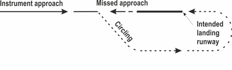
|
-
Start climbing and complete the turn to the intended landing runway (see figure).
-
Intercept the MAG track of that runway while climbing to 3000 FT AMSL.
-
In case a circling was made to RWY 05: when reaching 3000 FT AMSL turn left to intercept EEL 229 and proceed to OMFAR, hold or descend to 2000 FT AMSL in an outbound turn, intercept final approach and execute the instrument approach procedure again.
|
|
|
-
In case a circling was made to RWY 23: when reaching 3000 FT AMSL turn right to EEL. After passing EEL proceed to HECTI via EEL 051, hold or descend to 2000 FT AMSL in an outbound turn, intercept final approach and execute the instrument approach procedure again.
|
Note:
|
the indicated situation is applicable for an initial instrument approach to RWY 05. Circling approaches shall be executed south-east of the AD, unless otherwise instructed by ATC.
|
|
2.6 Instrument approach descriptions
|
|
|
-
Between the IAF and interception of final approach navigation is based on vectors provided by ATC, except in case of an RNAV procedure.
-
The ILS RWY 23 is not equipped with markers.
|
|
|
Note:
see also EHGG AD 2.22 paragraph 2.3.3.
Navigation in the initial and intermediate approach segment is primarily based on vectors provided by ATC. However, an RNAV approach procedure to RWY 23 is available. The use of the RNAV approach procedure is at ATC discretion. The procedure is only assigned in case the ILS is available. The vertical profile of the RNAV approach procedures is designed to enable a low noise continuous descent approach.
The ATC instruction "Cleared for TOLKO 2G approach RWY 23" is clearance to fly the published route and includes the clearance for the ILS instrument approach procedure to RWY 23. In this case the pilot is free to optimise the descent and speed within the constraints as laid down in the procedure description, with the objective to establish a low noise continuous descent approach.
|
2.6.3 Instrument approach segments
|
Note:
recommended navaid for selection of MAG station declination only.
Note:
for positions of GG-waypoints see relevant instrument approach charts.
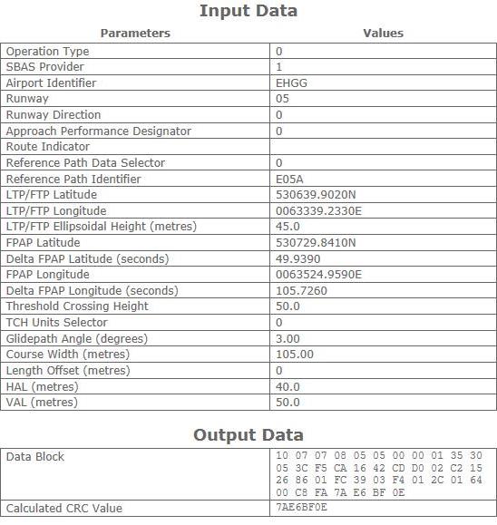
|
|
|
2.6.3.1.1 RNP approach RWY 05
|
|
Serial number
|
Path descriptor
|
WPT IDENT
|
Fly-over
|
Course/Track
°MAG / (°T)
|
Recom. navaid
|
DIST (NM)
|
Turn
|
Altitude (FT / FL)
|
Speed
(KIAS)
|
VPA (°) / TCH (FT)
|
NAV
specification
|
|
001
|
IF |
AMREG |
- |
- |
- |
- |
- |
+ 3000 |
- 220 |
- |
RNAV 1 |
|
002
|
TF |
TUVOX |
- |
139 / (141.8) |
- |
4.0 |
- |
+ 2000 |
- 190 |
- |
RNAV 1 |
|
003
|
IF |
VEXAR |
- |
- |
- |
- |
- |
+ 3000 |
- 220 |
- |
RNAV 1 |
|
004
|
TF |
TUVOX |
- |
319 / (321.9) |
- |
4.0 |
- |
+ 2000 |
- 190 |
- |
RNAV 1 |
|
005
|
IF |
TUVOX |
- |
- |
- |
- |
- |
+ 2000 |
- 190 |
- |
RNAV 1 |
|
006
|
TF |
GG509 |
- |
049 / (051.8) |
- |
4.0 |
- |
@ 2000 |
- |
- |
RNP APCH |
|
007
|
TF |
THR 05 |
Y |
049 / (051.7) |
- |
6.1 |
- |
- |
- |
-3.00 / 50 |
RNP APCH |
|
008
|
TF |
GG751 |
- |
049 / (051.8) |
- |
12.5 |
- |
@ 2000 |
- |
- |
RNP APCH |
FAS data block RWY 05
|
|
Additional Data
|
|
Parameters
|
Values
|
|
ICAO Code
|
EH |
|
LTP/FTP Orthometric Height (metres)
|
4.0 |
|
|
|
2.6.3.2.1 ILS approach RWY 23
|
|
Serial number
|
Path descriptor
|
WPT IDENT
|
Fly-over
|
Course/Track
°MAG / (°T)
|
Recom. navaid
|
DIST (NM)
|
Turn
|
Altitude (FT / FL)
|
Speed
(KIAS)
|
VPA (°) / TCH (FT)
|
NAV
specification
|
|
001
|
IF |
XOMBI |
- |
- |
- |
- |
- |
+ 3000 |
- 220 |
- |
RNAV 1 |
|
002
|
TF |
SIPLO |
- |
139 / (141.9) |
- |
4.0 |
- |
- |
- 190 |
- |
RNAV 1 |
|
003
|
CF |
GG512 |
- |
229 / (231.9) |
GRO |
4.0 |
- |
+ 2000 |
- |
- |
RNAV 1 |
|
004
|
IF |
IDAKA |
- |
- |
- |
- |
- |
+ 3000 |
- 220 |
- |
RNAV 1 |
|
005
|
TF |
SIPLO |
- |
322 / (322.0) |
- |
4.0 |
- |
- |
- 190 |
- |
RNAV 1 |
|
006
|
CF |
GG512 |
- |
229 / (231.9) |
GRO |
4.0 |
- |
+ 2000 |
- |
- |
RNAV 1 |
|
007
|
IF |
HECTI |
- |
- |
- |
- |
- |
- |
- |
- |
- |
|
008
|
CF |
GG512 |
- |
229 / (231.9) |
GRO |
2.8 |
- |
+ 2000 |
- |
- |
- |
|
009
|
CF |
THR 23 |
Y |
229 / (231.9) |
GRO |
6.1 |
- |
- |
- |
-3.00 / 50 |
- |
|
010
|
FM |
THR 23 |
- |
229 / (231.9) |
GRO |
- |
- |
@ 2000 |
- |
- |
- |
|
2.6.3.2.2 RNP approach RWY 23
|
|
Serial number
|
Path descriptor
|
WPT IDENT
|
Fly-over
|
Course/Track
°MAG / (°T)
|
Recom. navaid
|
DIST (NM)
|
Turn
|
Altitude (FT / FL)
|
Speed
(KIAS)
|
VPA (°) / TCH (FT)
|
NAV
specification
|
|
001
|
IF |
XOMBI |
- |
- |
- |
- |
- |
+ 3000 |
- 220 |
- |
RNAV 1 |
|
002
|
TF |
SIPLO |
- |
139 / (141.9) |
- |
4.0 |
- |
+ 2000 |
- 190 |
- |
RNAV 1 |
|
003
|
IF |
IDAKA |
- |
- |
- |
- |
- |
+ 3000 |
- 220 |
- |
RNAV 1 |
|
004
|
TF |
SIPLO |
- |
319 / (322.0) |
- |
4.0 |
- |
+ 2000 |
- 190 |
- |
RNAV 1 |
|
005
|
IF |
SIPLO |
- |
- |
- |
- |
- |
+ 2000 |
- 190 |
- |
RNAV 1 |
|
006
|
TF |
GG512 |
- |
229 / (231.9) |
- |
4.0 |
- |
@ 2000 |
- |
- |
RNP APCH |
|
007
|
TF |
THR 23 |
Y |
229 / (232.0) |
- |
6.1 |
- |
- |
- |
-3.00 / 50 |
RNP APCH |
|
008
|
TF |
GG752 |
- |
229 / (231.9) |
- |
12.5 |
- |
@ 2000 |
- |
- |
RNP APCH |
|
|
|
|
Additional Data
|
|
Parameters
|
Values
|
|
ICAO Code
|
EH |
|
LTP/FTP Orthometric Height (metres)
|
3.8 |
|
2.6.3.2.3 TOLKO2G approach RWY 23
|
|
Serial number
|
Path descriptor
|
WPT IDENT
|
Fly-over
|
Course/Track
°MAG / (°T)
|
Recom. navaid
|
DIST (NM)
|
Turn
|
Altitude (FT / FL)
|
Speed
(KIAS)
|
VPA (°) / TCH (FT)
|
NAV
specification
|
|
001
|
IF |
TOLKO |
- |
- |
- |
- |
- |
+ FL 080 |
- 250 |
- |
- |
|
002
|
TF |
GETSI |
- |
031 / (033.6) |
- |
8.5 |
- |
- |
- |
- |
RNAV 1 |
|
003
|
TF |
GG740 |
- |
061 / (063.7) |
- |
9.5 |
- |
+ 3500 |
- 220 |
- |
RNAV 1 |
|
004
|
TF |
GG741 |
- |
139 / (142.0) |
- |
4.0 |
- |
- |
- |
- |
RNAV 1 |
|
005
|
TF |
GG742 |
- |
199 / (202.0) |
- |
3.0 |
- |
+ 2000 |
- |
- |
RNAV 1 |
|
006
|
CF |
GG512 |
- |
229 / (231.9) |
GRO |
2.0 |
- |
@ 2000 |
- |
- |
RNAV 1 |
|
007
|
CF |
THR 23 |
Y |
229 / (231.9) |
GRO |
6.1 |
- |
- |
- |
- 3.00 / 50 |
- |
|
008
|
FM |
THR 23 |
- |
229 / (231.9 |
EEL |
- |
- |
@ 2000 |
- |
- |
- |
|
3 LOW VISIBILITY PROCEDURES
|
During periods of low visibility the overall ATC capacity is reduced. To guarantee aircraft safety and optimal use of ATC capacity, Groningen Airport Eelde uses ATC low visibility procedures. These procedures are based on ICAO DOC 9476/1 (Surface Movement Guidance and Control Manual) and ECAC DOC 17 (Ground operations in limited visibility conditions).
The ATC low visibility procedures are categorised in four phases (A , B, C, and D), that are based on visibility or RVR values and ceiling.
The ATC low visibility procedures become effective when the general visibility is equal to or below 2000 M, or the lowest RVR is equal to or below 1500 M.
|
|
Phase
|
Conditions
|
Procedure
|
|
A
|
550 M <= VIS <= 2000 M or
lowest RVR <= 1500 M
|
No conditional clearances. No intersection departures. When RVR drops below 800 M no take-off clearance will be given. |
|
B
|
Lowest RVR < 550 M and/or
ceiling < 200 FT
|
ATC may give permission to taxi if no other aircraft is moving or expected to be moving in the manoeuvring area, unless both aircraft are continuously visible to TWR at all times. |
|
C
|
Lowest RVR < 350 M |
No landings allowed. |
|
D
|
Lowest RVR < 200 M |
Taxiing only allowed under guidance of a follow-me car. |
|
|
|
|
|
To accommodate the conduct and to increase the amount of training flights to be handled by ATC, a training area has been established within the lateral limits of the Eelde TMA. The upper limit of the Eelde TMA can temporarily be changed to FL 085 to enlarge the training area. Assignment of the area depends on circumstances as nature of training, aircraft performance, traffic load, pilots request etc.
Note:
training and test flights including go-arounds PPR from airport manager.
Note:
IFR-training flights outside operational hours Eelde Approach: PPR from ATC, TEL: +31 (0)50 309 9229.
Note:
to avoid noise disturbances pilots shall adhere to the IFR and VFR approach and departure procedures and traffic circuits as depicted.
|
4.2 Communication failure
|
|
|
The pilot of an IFR flight shall follow the general procedures for IFR flights (see ENR 1.3 paragraph "Communication Failure").
The instrument approach procedures from HECTI or OMFAR may be followed by a visual or circling approach to the main landing runway or if not acceptable to the most convenient runway.
|
|
|
In addition to the general procedures, the pilot shall:
-
proceed to the fix of the main landing runway (HECTI for RWY 23, OMFAR for RWY 05).
-
maintain the last cleared and acknowledged flight level or altitude.
-
after arrival over the fix, intercept the holding pattern.
-
commence descent to 2000 FT AMSL at the EAT last received and acknowledged.
-
after reaching 2000 FT AMSL leave the holding fix and carry out an instrument approach procedure to the appropriate runway (see relevant instrument approach chart).
|
4.2.3 Traffic vectored to final approach
|
In addition to the general procedures, the pilot shall:
-
maintain the last cleared and acknowledged level or altitude.
-
proceed to the fix of the assigned landing runway (HECTI for RWY 23 and OMFAR for RWY 05).
-
after arrival over the fix, descend to 2000 FT AMSL, if applicable.
-
after reaching 2000 FT, leave the fix and carry out an instrument approach procedure to the appropriate runway (see relevant instrument approach chart).
|
5 VFR FLIGHT PROCEDURES AND REGULATIONS
|
Note:
for visual procedures and visual traffic circuits see chart VAC - VFR procedures and VFR TFC circuits.
|
|
|
-
All VFR flights within the Eelde CTR shall submit a flight plan (see ENR 1.10).
-
Eelde CTR has been designated as controlled airspace (class C).
-
Flights within the Eelde CTR should maintain two-way radio communication with Eelde TWR, unless they have been exempted by ATS Eelde. This exemption will only be granted in extraordinary circumstances.
-
Prior permission is required from Eelde TWR for all VFR operations in the CTR.
-
All aircraft performing VFR flights in the Eelde CTR must show their landing lights.
-
All VFR flights conducted within the Eelde CTR shall be executed at or below 1500 FT AMSL.
-
VFR flights shall be carried out via the arrival/departure routes unless otherwise instructed by ATC or on pilots request.
-
To avoid noise disturbances pilots shall adhere to the VFR approach and departure procedures and traffic circuits as depicted.
-
Built-up areas shall be avoided as much as possible.
-
Marked areas shall be avoided.
-
IFR area: VFR flights within the CTR may be instructed by ATC to stay clear of this area. The IFR area is indicated on the chart VAC - VFR procedures.
-
Pilots are urgently requested not to execute VFR flights in the vicinity of the published instrument arrival and departure routes within the Eelde TMA, which are published in EHGG AD 2.24.
-
Training and test flights including missed approaches PPR from airport manager.
-
VFR reporting points positions:
|
VFR reporting point
|
Position
|
|
NOVEMBER
|
531003N 0063523E |
|
PAPA
|
530927N 0063213E |
|
ROMEO
|
530034N 0063608E |
|
TANGO
|
530446N 0063745E |
|
UNIFORM
|
530108N 0063248E |
|
VICTOR
|
530449N 0063610E |
|
X-RAY
|
531235N 0062736E |
|
YANKEE
|
531414N 0063905E |
Note:
all VFR flights transiting the Eelde TMA are urgently requested to contact Eelde APP; MON-FRI on 120.305 and SAT-SUN on 118.705.
|
5.2 Visual departure procedures
|
-
Pilots must have obtained start-up clearance from ATC before starting engines. A request for start-up shall be made to Eelde Delivery, clearance for start-up will either be issued immediately or at a specified time depending on traffic. A request for start-up includes:
-
aircraft identification and type (e.g. PHJUR Cessna 172).
-
position (e.g. in front of tower).
-
flight rules (e.g. VFR).
-
destination (e.g. Rotterdam).
-
ATIS information (e.g. information E).
-
request start-up (request start-up).
-
Taxiing on taxiways: pilots of aircraft intending to taxi on the taxiways shall obtain a clearance from Eelde TWR.
-
Unless otherwise instructed or approved climb after take-off to 1000 FT AMSL.
-
Make the shortest turn to join the instructed departure at or before PAPA or VICTOR.
-
Cross PAPA or VICTOR at 1000 FT AMSL and maintain 1000 FT AMSL until outside CTR.
-
Report PAPA and VICTOR on ATC request.
-
Report leaving the CTR over the designated reporting point.
Note:
when joining UNIFORM Departure, the railway Groningen/Assen via Haren, Glimmen and Tynaarlo shall not be crossed (see also Caution in chart VAC - VFR procedures).
|
5.3 Visual approach procedures
|
-
Contact Eelde TWR 2 minutes before reaching the CTR boundary for permission to enter the CTR.
-
Unless otherwise instructed, enter the CTR at 1500 FT AMSL and maintain.
-
Descend to circuit altitude and join the circuit as instructed by ATC.
Note:
unless otherwise instructed the circuit altitude is 1000 FT for light propeller aircraft (no turboprop) with MAX AUW of 6000 KG, and 1500 FT for jet, turboprop and other aircraft (with MAX AUW > 6000 KG).
-
In case of missed approach climb straight ahead to MAX 1000 FT AMSL and inform ATC.
|
|
|
|
|
-
Report downwind and intentions (e.g. ‘touch-and-go’, ‘full-stop’ or ‘practice go-around’).
-
ATC will issue a sequence number and traffic to follow. Do not turn base before the traffic to follow or before receiving a sequence number.
-
After receiving your sequence number, turn base and final at own discretion.
-
Reporting final is compulsory when no landing clearance is received.
-
In case of missed approach: inform ATC immediately while climbing to the published circuit altitude.
Note:
the circuit may be extended at ATC discretion and/or altitudes of 500 FT or 1500 FT AMSL may be issued.
|
|
|
Note:
landing traffic RWY 05 should not vacate the runway via TWY C unless otherwise instructed by ATC.
For light propeller aircraft (no turboprop, MAX AUW 6000 KG):
-
Righthand circuit at 1000 FT AMSL.
-
Aim for landing abeam or beyond intersection S3, unless an extended downwind is flown.
For other aircraft:
-
Righthand circuit at 1500 FT AMSL.
-
At 500 FT AMSL turn left to track 047° MAG.
-
When abeam orange circuitmarker turn right to join the circuit.
Traffic inbound via Y and N should expect a lefthand circuit.
|
|
|
For light propeller aircraft (no turboprop, MAX AUW 6000 KG):
-
Lefthand circuit at 1000 FT AMSL.
For other aircraft:
-
Lefthand circuit at 1500 FT AMSL.
-
Turn to final beyond the orange circuitmarker.
Traffic shall not execute a threshold baseleg for the righthand circuit.
|
5.5 Communication failure procedures
|
|
|
|
|
|
|
In case of communication failure adhere to the departure instructions. If the departure instructions contain a clearance limit in the CTR, act in accordance with paragraph 5.5.4.
|
|
|
5.5.3.1 Via ROMEO Arrival
|
-
In case of communication failure before joining the circuit leave the CTR according to the UNIFORM Departure and divert to an appropriate aerodrome.
-
In case of communication failure over or after a position from where to join the circuit (this is past the compulsory reporting point TANGO or OVERHEAD) execute a circuit for the last received and acknowledged runway as short as practicable. Make a full stop landing and vacate as soon as possible. In case of go-around execute a similar circuit (be aware of the fact that your flightpath could interfere with the flightpath of other aerodrome traffic).
|
5.5.3.2 Via YANKEE Arrival
|
-
In case of communication failure before joining the circuit leave the CTR according to the X-RAY Departure and divert to an appropriate aerodrome.
-
In case of communication failure over or after a position from where to join the circuit (this is past compulsory reporting point NOVEMBER or OVERHEAD) act in accordance with paragraph 5.5.3.1 item b.
|
5.5.3.3 Via a different route to the field
|
-
In case of communication failure before joining the circuit act in accordance with paragraph 5.5.4.
-
In case of communication failure over or after a position from where to join the circuit act in accordance with paragraph 5.5.3.1 item b.
|
5.5.4 VFR crossing the CTR
|
In case of communication failure leave the CTR via the shortest route, maintain altitude until outside the CTR, do not cross runway centre line 05/23 or IFR area and proceed to an appropriate aerodrome.
|
EHGG AD 2.23 ADDITIONAL INFORMATION
|
|
1 CAUTIONS AND ADDITIONAL INFORMATION
|
-
For details of the low flying areas see ENR 5.1 and ENR 5.2.
-
Parachute jumping may take place as stated in ENR 5.5 and/or as promulgated by NOTAM.
-
When approaching RWY 23 possible sun reflection and glare caused by solar panels right of the runway; especially in the period MAR-APR and SEP-OCT during the evening.
-
Pilots shall be aware that in the vicinity of the aerodrome ATC gives priority to:
-
aircraft in state of an emergency;
-
hospital and police aircraft with the status priority or scramble;
-
aircraft engaged in SAR operations.
-
Grass cutting will take place at irregular times.
|
|
|
A runway turnpad is situated at the end of RWY 23. This turnpad shall be used by aircraft with wingspan > 24 M in case of:
-
full-length take-off RWY 05;
-
landing RWY 23 and missing exit TWY C;
-
rejected take-off RWY 23 and missing exit TWY C.
Note:
the runway turnpad centre line marking and lighting is not fully compliant to EASA regulation. Aircraft using the turnpad shall disregard the turnpad centre line marking and lighting. Turning on the turnpad is at own discretion.
|
3 GROUND HANDLING COMPANIES
|
-
Full service handling agent
(all ACFT types). Handling passengers, cargo and general aviation; cargo facilities AVBL O/R.
|
Post:
|
Groningen Airport Eelde Handling |
|
Tel:
|
+31 (0)50 309 5433 |
|
Email:
|
[email protected]
|
|
SITA:
|
GRQAPXH |
|
Note:
|
Groningen Handling 131.580
|
-
Fixed base operator
(handling general aviation aircraft MAX wingspan 24 M):
|
Post:
|
Ground Ace |
|
Tel:
|
+31 (0)50 308 0075 |
|
Fax:
|
+31 (0)50 308 0076 |
|
Email:
|
[email protected]
|
|
EHGG AD 2.24 AERONAUTICAL CHARTS RELATED TO AN AERODROME
|
|
Charts
|
Pages
|
ADC
|
|
APDC
|
|
AOC RWY 05-23
|
|
SID
|
|
SID RWY 05
|
|
SID RWY 23
|
|
STAR
|
|
ATCSMAC
|
|
IAC RNP RWY 05
|
|
IAC VOR RWY 05
|
|
IAC ILS or LOC RWY 23
|
|
IAC TOLKO 2G approach ILS RWY 23
|
|
IAC RNP RWY 23
|
|
IAC VOR RWY 23
|
|
VAC - VFR procedures
|
|
VFR TFC circuits RWY 05-23
|
|
|
EHGG AD 2.25 VISUAL SEGMENT SURFACE (VSS) PENETRATION
|
|
|
|