ENR 1.6 ATS SURVEILLANCE SERVICES AND PROCEDURES
1 PRIMARY RADAR
1.1 Use of radar in the air traffic control service
ATC will normally use radar derived information in the provision of air traffic control services. The applicable radar separation minima vary from 3 NM to 6 NM depending on the distance from the appropriate radar station.
Radar vectors and speed instructions may be necessary to establish and maintain radar separation. These instructions, also if they might result in differences from published procedures, shall be complied with.
ATC surveillance minimum altitude charts (SMAC) are published for EHAM, EHBK, EHGG, EHLE and EHRD.
The final approach vectoring area (FAVA) is an area which provides 500 feet obstacle clearance in the transition from an ATC vector to the final approach with a maximum ILS localizer interception angle of 30 degrees.
1.2 Minimum vectoring altitudes (MVA)
In the Amsterdam FIR the following definition of minimum vectoring altitude (MVA) is applicable:
The minimum vectoring altitude is the lowest altitude or flight level that may be used by ATC for vectoring IFR flights in a certain area of controlled airspace, taking into account the altitude required for obstacle clearance and the airspace classification.
I.e. the MVA is the lowest altitude that under normal circumstances is assigned by ATC to pilots of IFR flights, until the point where the pilot will resume his own navigation, for instance on final approach or in the circuit.
- Terminal control areas (TMAs)
Eelde TMA 2000 FT AMSL 1) Eindhoven TMA 1 2000 FT AMSL Eindhoven TMA 2 transition level Eindhoven TMA 3 transition level Eindhoven TMA 4 FL 060 Lelystad TMA 1 Refer to AD 2.EHLE-SMAC Lelystad TMA 2 2000 FT AMSL Lelystad TMA 3 2000 FT AMSL Lelystad TMA 4 3000 FT AMSL Lelystad TMA 5 FL 050 Maastricht TMA 1 2000 FT AMSL 4) Nieuw Milligen TMA A 2000 FT AMSL 2) Nieuw Milligen TMA B 2000 FT AMSL 1) Nieuw Milligen TMA C 2000 FT AMSL 1) Nieuw Milligen TMA D 2000 FT AMSL 3) Nieuw Milligen TMA E 2000 FT AMSL Nieuw Milligen TMA G1 2000 FT AMSL Nieuw Milligen TMA G2 transition level Rotterdam TMA 1 2000 FT AMSL Rotterdam TMA 2 3000 FT AMSL Rotterdam TMA 3 transition level Schiphol TMA 1 2000 FT AMSL Schiphol TMA 2 transition level Schiphol TMA 3 3000 FT AMSL Schiphol TMA 4 transition level Schiphol TMA 5 FL 060 Schiphol TMA 6 transition level Schiphol TMA 7 Refer to Schiphol TMA 1 Schiphol TMA 8 Refer to Schiphol TMA 1 - Control zones (CTRs)
Eelde CTR Refer to AD 2.EHGG-SMAC Lelystad CTR 1 and 2 Refer to AD 2.EHLE-SMAC Maastricht CTR Refer to AD 2.EHBK-SMAC Rotterdam CTR Refer to AD 2.EHRD-SMAC Schiphol CTR Refer to AD 2.EHAM-SMAC
- Within a radius of 3 NM around 525410N 0062413E (obstacle Smilde): 2100 FT AMSL.
- Within the part of Nieuw Milligen TMA A above EHTX: transition level.
- Within a radius of 3 NM around 520036N 0050313E (obstacle Lopik): 2300 FT AMSL.
- Southeast of Maastricht CTR: 2500 and 2600 FT AMSL.
1.3 Use of radar in the flight information service
Amsterdam FIC may use radar derived information in the provision of flight information service. Radar serves only as an aid to provide aircraft with more accurate flight information. It does not relieve the pilot-in-command of an aircraft of any of his responsibilities and he has to make the final decision regarding any suggested alteration of flight plan.
2 SECONDARY SURVEILLANCE RADAR (SSR)
2.1 Transponder operating procedures
2.1.1 Normal procedures
- The provisions of ICAO (Aircraft Operations Volume I, Flight Procedures, part VIII, chapter 1) apply.
- Except when conditions in item c and d are met, pilots shall operate transponders in accordance with ATC instructions. In particular, when entering the Amsterdam FIR, pilots who have already received specific instructions from ATC concerning the setting of the transponder shall maintain that setting until otherwise instructed.
- IFR flights about to enter the Amsterdam FIR who have not received specific instructions from ATC concerning the setting of the transponder shall operate the transponder on mode A code 2000 before entry and maintain that code setting until otherwise instructed.
- VFR flights in the Amsterdam FIR equipped with an operational mode S transponder shall activate the transponder and select mode A code 7000 during all flight stages from departure until touch down, unless otherwise prescribed or instructed. This includes flights in airspace exempted from the mandatory transponder carriage.
- Gliders starting with the use of a winch are advised to activate the transponder only after the winch is disconnected. The high climb-rate during a winch-start can lead to unwanted “resolution advisory” warnings on ACAS systems.
- In accordance with ICAO Doc 8168 (PANS-OPS) Volume I, part III, section 3, chapter 1.3: the flight crew of aircraft equipped with mode S transponders shall set the aircraft identification in the transponder. This setting shall correspond to the aircraft identification specified in item 7 of the ICAO flight plan or, if no flight plan has been filed, the aircraft registration. In order to be interpreted properly, there must be no spaces between the designator letters and flight number, nor any additional/superfluous zeros preceding the flight number. For details see ENR 1.10 FLIGHT PLANNING, 3.2.1 ITEM 7: aircraft identification.
- In case the aircraft identification can be entered manually, entry should be part of the start-up procedures.
- Correct setting of aircraft identification is essential for identification and correlation (of radar track with flight plan data). An incorrect setting of the aircraft identification will be reported to the Dutch aviation authorities.
2.1.2 Emergency procedures
- If the pilot of an aircraft encountering a state of emergency has previously been directed by ATC to operate the transponder on a specific code, this code setting shall be maintained until otherwise advised.
In all other circumstances, the transponder shall be set on mode A code 7700. - Notwithstanding the procedure in item a. above, a pilot may select mode A code 7700 whenever the nature of the emergency is such that this appears to him to be the most suitable course of action.
- Pilots of aircraft in-flight subjected to unlawful interference shall endeavour to set the transponder to mode A code 7500 to give indication of the situation, unless circumstances warrant the use of code 7700.
Mode C shall always be activated.
2.1.3 Radio communication failure procedures
In the event of an aircraft radio receiver failure, a pilot shall select mode A code 7600 and follow established procedures; subsequent control of the aircraft will be based on those procedures.
Mode C shall always be activated.
2.1.4 SSR transponder failure
Because of the dominating role of SSR in radar data processing it is almost impossible to accommodate a flight with a failing transponder in an ATC environment. Pilots have to take this into account when interpreting the procedures indicated below.
- In particular in the case of an observed failure immediately after take-off, ATC will normally not be in a position to allow continuation of the flight to destination.
- In case of failure which occurs during flight, pilots may expect that ATC units will endeavour to provide for continuation of the flight to the aerodrome of first intended landing in accordance with the flight plan.
2.2 Mode A code assignment method
Mode A codes will be assigned in accordance with the modified code allotment plan for the EUR region, which is based on the so-called originating region code assignment method (ORCAM). Codes protected for international transit in use (transit codes), which are assigned to overflying or inbound flights, will be retained by ATC.
2.3 Flight plan notification
For flights intending to enter the Amsterdam FIR, the aircraft SSR capability shall be indicated in item 10 of the flight plan.
2.4 Mode S radar coverage
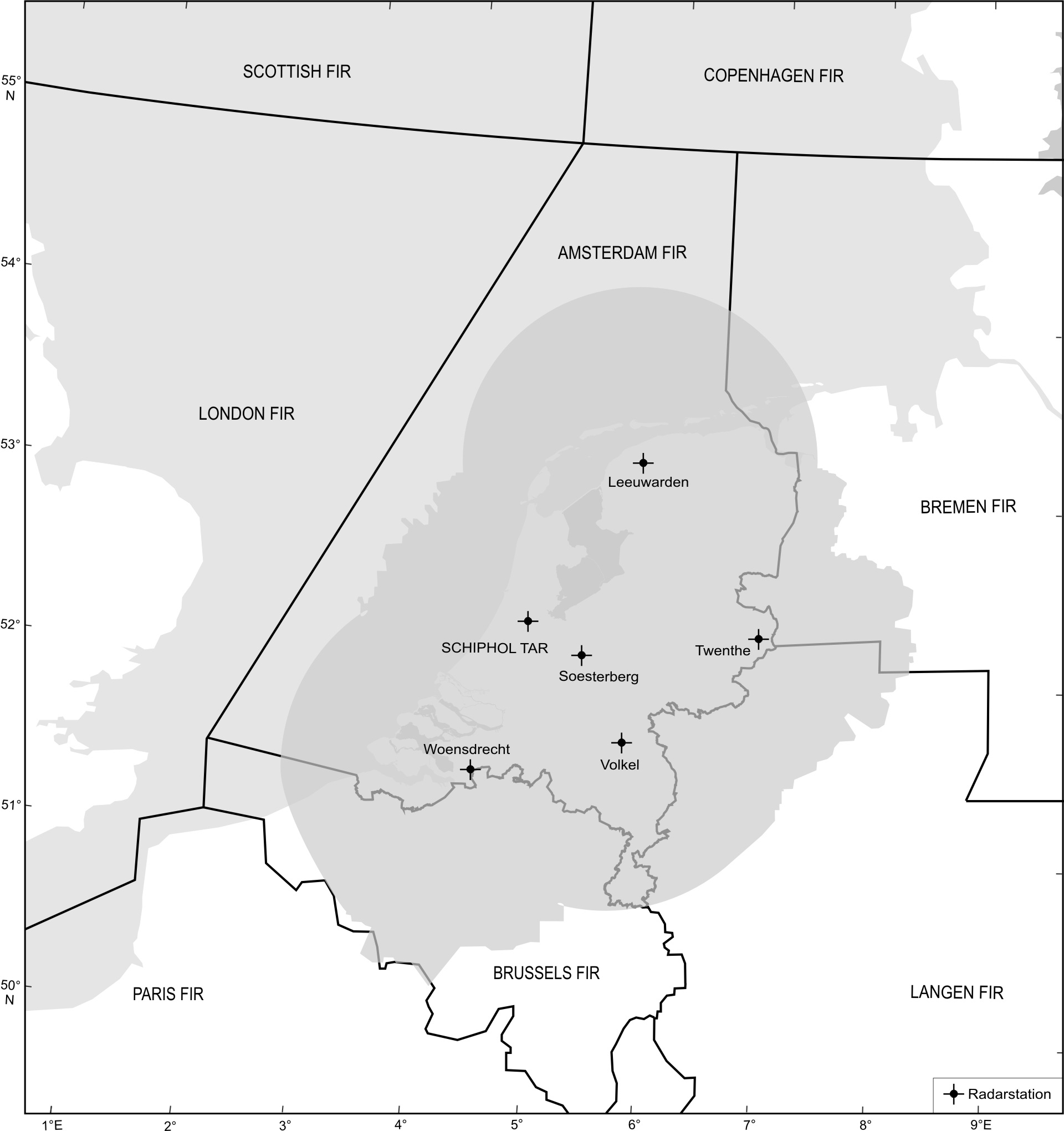
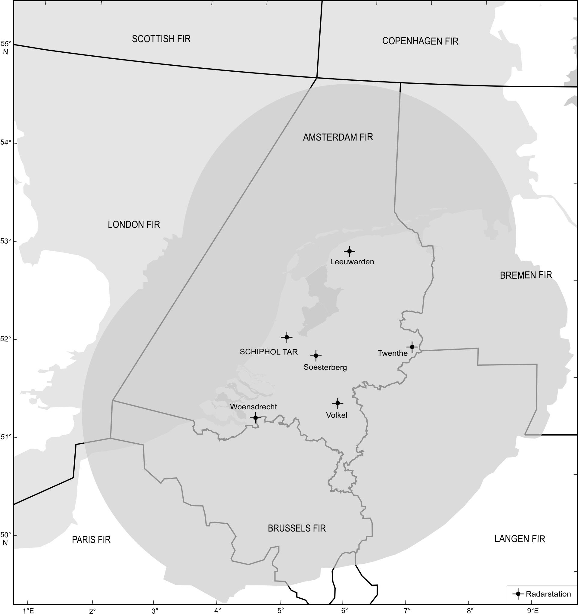
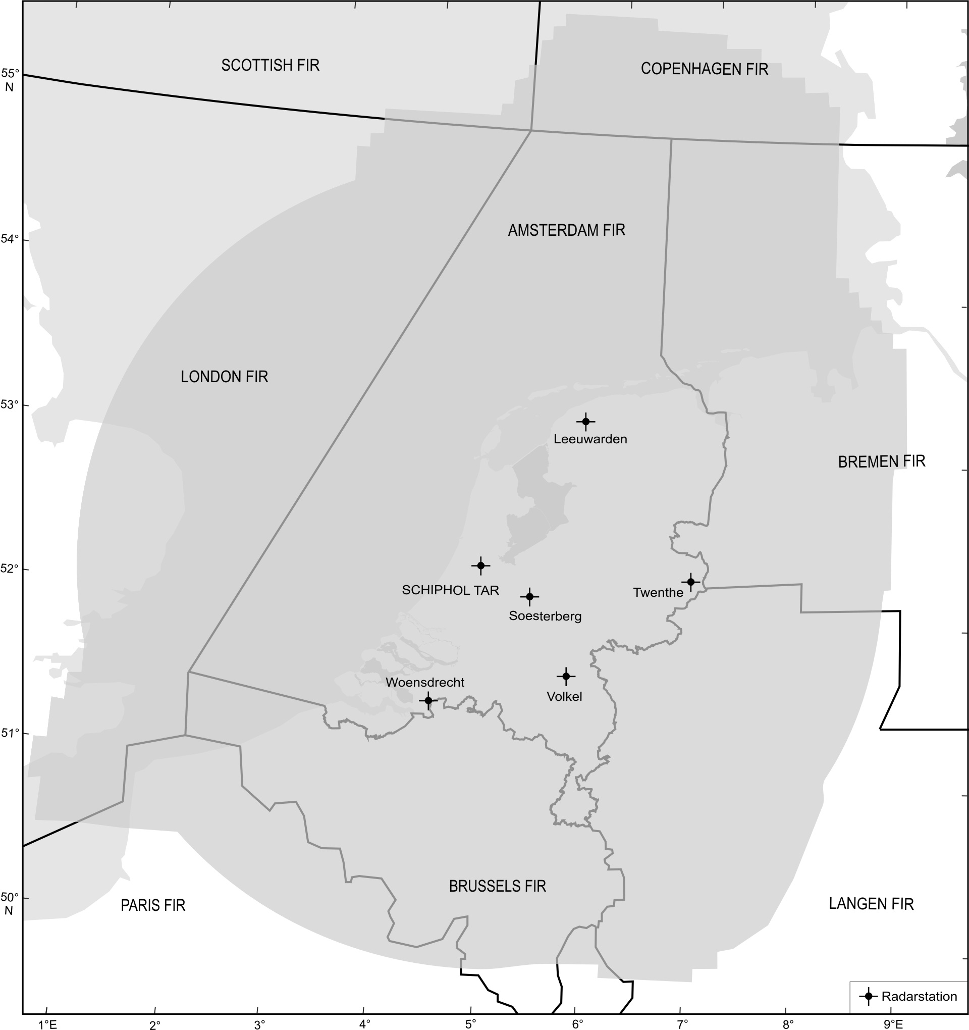
Mode S radar coverage in the Amsterdam FIR is shown in the following radar coverage maps of three horizontal sections: 1500 ft AMSL, FL 055 and FL 245.
 | Mode S radar coverage at 1500 ft AMSL |
 | Mode S radar coverage at FL 055 |
 | Mode S radar coverage at FL 245 |
3 AUTOMATIC DEPENDENT SURVEILLANCE - BROADCAST (ADS-B)
To be developed.
4 OTHER RELEVANT INFORMATION AND PROCEDURES
NIL.