EHTX - TEXEL/TEXEL
EHTX AD 2.1 AERODROME LOCATION INDICATOR AND NAME
EHTX AD 2.2 AERODROME GEOGRAPHICAL AND ADMINISTRATIVE DATA
1
ARP coordinates and site at AD
530655N 0045001E
115 DEG GEO 520 M from AD office.
2
Direction and distance from (city)
3.5 NM NNE of Den Burg.
3
Elevation / reference temperature
ELEV: 2 FT AMSL / T: 19.5 °C
4
Geoid undulation at AD ELEV PSN
NIL
5
MAG VAR / annual change
2° E (2025) / 0.2° E
6
AD operator, address, telephone, telefax, email address, AFS, URL
TEXEL AIRPORT LTD.
POSTWEG 120 
1795 JS DE COCKSDORP, TEXEL
THE NETHERLANDS

TEL: +31 (0)222 311 267
email: [email protected]
URL: https://www.texelairport.nl

7
Types of traffic permitted (IFR/VFR)
VFR
8
Remarks
  1. Aerodrome available for national and international civil air traffic with all types of aircraft up to 6000 KG AUW and gliders.
  2. Aerodrome authority can admit aircraft with higher AUW.
EHTX AD 2.3 OPERATIONAL HOURS
1
AD operator
MON-SAT 0800-1800 (MON-SAT 0700-1700) during UDP
SUN HOL 0900-1800 (SUN HOL 0800-1700) during UDP

2
Customs and immigration
MON-SAT 0800-1800 (MON-SAT 0700-1700) during UDP
SUN HOL 0900-1800 (SUN HOL 0800-1700) during UDP

3
Health and sanitation
NIL
4
AIS briefing office
H24
5
ATS reporting office (ARO)
H24
6
MET briefing office
NIL
7
ATS
NIL
8
Fuelling
MON-SAT 0800-1800 (MON-SAT 0700-1700) during UDP
SUN HOL 0900-1800 (SUN HOL 0800-1700) during UDP

9
Handling
NIL
10
Security
NIL
11
De-icing
NIL
12
Remarks
AD operator
  • Outside AD OPR HR: O/R.
Customs and immigration
  • 2 HR PN.

MET briefing office
  • Self-briefing, AD OPR HR.
PN means permission from and/or in case of customs etc. notification other than by (VFR) flight plans to aerodrome authority as appropriate.
EHTX AD 2.4 HANDLING SERVICES AND FACILITIES
1
Cargo-handling facilities
NIL
2
Fuel / oil types
Fuel: JET A-1, AVGAS 100LL, MOGAS Euro 98
Oil: NIL
3
Fuelling facilities/capacity
Jet A-1: 50 000 litres.
AVGAS 100LL: 50 000 litres.

Mogas Euro 98: 500 litres.
4
De-icing facilities
NIL
5
Hangar space for visiting aircraft
Limited AVBL.
6
Repair facilities for visiting aircraft
AVBL O/R.
7
Remarks
NIL
EHTX AD 2.5 PASSENGER FACILITIES
1
Hotels
10 rooms at the aerodrome. Sufficient accommodation in Den Burg and De Koog.
2
Restaurants
At the aerodrome.
3
Transportation
Taxi (on request), bus and bicycle.
4
Medical facilities
First aid AVBL.
5
Bank and post office
Bank: In Den Burg.
Post: In Den Burg.
6
Tourist office
In Den Burg.
7
Remarks
NIL
EHTX AD 2.6 RESCUE AND FIREFIGHTING SERVICES
1
AD category for firefighting
CAT 3
2
Rescue equipment
NIL
3
Capability for removal of disabled aircraft
Limited AVBL.
4
Remarks
AD category for fire fighting
  • 2 fire trucks.
EHTX AD 2.7 RUNWAY SURFACE CONDITION ASSESSMENT AND REPORTING, AND SNOW PLAN
1
Types of clearing equipment
NIL
2
Clearance priorities
NIL
3
Use of material for movement area surface treatment
NIL
4
Specially prepared winter runways
NIL
5
Remarks
NIL
EHTX AD 2.8 APRONS, TAXIWAYS AND CHECK LOCATIONS/POSITIONS DATA
1
Apron designation, surface and strength
Designation
Stand
Surface
Strength
NIL
NIL
NIL
NIL
2
Taxiway designation, width, surface and strength
Designation of TWY
Width
Surface
Strength
ALL TAXIWAYS
NIL
Grass
NIL
3
Altimeter checkpoint location and elevation
NIL
4
VOR checkpoints
NIL
5
INS checkpoints
NIL
6
Remarks
NIL
EHTX AD 2.9 SURFACE MOVEMENT GUIDANCE AND CONTROL SYSTEM AND MARKINGS
1
Use of aircraft stand ID signs, TWY guide lines and visual docking/parking guidance system at aircraft stands
NIL
2
RWY and TWY markings and LGT
RWY markings
  • white cones.
  • black/white markers.
  • take-off position orange cones.
RWY LGT
  • runway threshold identification lights (FLG W, weather depending).
TWY markings
  • blue cones.
TWY LGT
  • NIL
3
Stop bars
NIL
4
Remarks
NIL
EHTX AD 2.10 AERODROME OBSTACLES
For obstacles at and in the vicinity of the aerodrome see the aerodrome chart.
Area 2
OBST ID / designation
OBST type
OBST position
ELEV/HGT (FT)
Markings /
type, colour LGT

Remarks
1
2
3
4
5
6
NIL
Area 3
OBST ID / designation
OBST type
OBST position
ELEV/HGT (FT)
Markings /
type, colour LGT

Remarks
1
2
3
4
5
6
NIL
EHTX AD 2.11 METEOROLOGICAL INFORMATION PROVIDED
1
Associated MET office
NIL
2
Hours of service
MET office outside hours

Hours of service
NIL


MET office outside hours
NIL

3
Office responsible for TAF preparation
Period of validity


NIL
4
Trend forecast
Interval of issuance

NIL
5
Briefing/consultation provided
NIL
6
Flight documentation
Language(s) used

NIL
7
Charts and other information available for briefing or consultation
NIL
8
Supplementary equipment available for providing information
NIL
9
ATS units provided with information
NIL
10
Additional information (limitation of service, etc.)
NIL
EHTX AD 2.12 RUNWAY PHYSICAL CHARACTERISTICS
RWY designation
True BRG
Dimensions of RWY (M)
Strength (PCN) and surface of RWY and SWY
THR coordinates
RWY end coordinates
THR GUND

THR ELEV and highest ELEV of TDZ of precision APCH RWY
1
2
3
4
5
6
03
036.00°
1109 x 40
RWY: 6000 KG
Grass
SWY: NIL
THR: NIL
RWY end: NIL
THR GUND: NIL
THR: NIL
TDZ: NIL
21
216.00°
1109 x 40
RWY: 6000 KG
Grass
SWY: NIL
THR: NIL
RWY end: NIL
THR GUND: NIL
THR: NIL
TDZ: NIL
12
126.00°
592 x 30
RWY: 6000 KG
Grass
SWY: NIL
THR: NIL
RWY end: NIL
THR GUND: NIL
THR: NIL
TDZ: NIL
30
306.00°
592 x 30
RWY: 6000 KG
Grass
SWY: NIL
THR: NIL
RWY end: NIL
THR GUND: NIL
THR: NIL
TDZ: NIL
RWY designation
Slope of RWY-SWY
SWY dimensions (M)
CWY dimensions (M)
Strip dimensions (M)
RESA dimensions (M)
Location and description of arresting system
OFZ
1
7
8
9
10
11
12
13
03
NIL
NIL
60 x 80
1169 x 80
30 x 80
NIL
NIL
21
NIL
NIL
60 x 80
1169 x 80
30 x 80
NIL
NIL
12
NIL
NIL
30 x 60
622 x 60
30 x 60
NIL
NIL
30
NIL
NIL
30 x 60
622 x 60
30 x 60
NIL
NIL
RWY designation
Remarks
1
14
03
Strength (PCN) and surface of RWY
-    Bearing strength.
-    MAX tyre pressure 0.56 MPa.
-    When surface conditions so permit, the aerodrome manager can admit aircraft with a higher MAUW and a higher tyre pressure.

21
Strength (PCN) and surface of RWY
-    Bearing strength.
-    MAX tyre pressure 0.56 MPa.
-    When surface conditions so permit, the aerodrome manager can admit aircraft with a higher MAUW and a higher tyre pressure.

12
Strength (PCN) and surface of RWY
-    Bearing strength.
-    MAX tyre pressure 0.56 MPa.
-    When surface conditions so permit, the aerodrome manager can admit aircraft with a higher MAUW and a higher tyre pressure.

30
Strength (PCN) and surface of RWY
-    Bearing strength.
-    MAX tyre pressure 0.56 MPa.
-    When surface conditions so permit, the aerodrome manager can admit aircraft with a higher MAUW and a higher tyre pressure.

EHTX AD 2.13 DECLARED DISTANCES
RWY designator
TORA
(M)

TODA
(M)

ASDA
(M)

LDA
(M)

Remarks
1
2
3
4
5
6
03
1109
1169
1109
1049
For take-off line up BTN orange cones.
DTHR 60 M.
21
1109
1169
1109
1049
For take-off line up BTN orange cones.
DTHR 60 M.
12
592
622
592
562
For take-off line up BTN orange cones.
DTHR 30 M.
30
592
622
592
562
For take-off line up BTN orange cones.
DTHR 30 M.
EHTX AD 2.14 APPROACH AND RUNWAY LIGHTING
RWY
designator

APCH LGT
type
length
INTST

THR LGT
colour
WBAR

VASIS
location/slope
MEHT

TDZ LGT
length

RWY CL LGT
length
spacing
colour
INTST

1
2
3
4
5
6
03
NIL
NIL
NIL
NIL
NIL
21
NIL
NIL
NIL
NIL
NIL
12
NIL
NIL
NIL
NIL
NIL
30
NIL
NIL
NIL
NIL
NIL
RWY
designator

RWY edge LGT
length
spacing
colour
INTST

RWY end LGT
colour
WBAR

SWY LGT
length
colour

Remarks
1
7
8
9
10
03
NIL
NIL
NIL
NIL
21
NIL
NIL
NIL
NIL
12
NIL
NIL
NIL
NIL
30
NIL
NIL
NIL
NIL
EHTX AD 2.15 OTHER LIGHTING, SECONDARY POWER SUPPLY
1
ABN/IBN location, characteristics and hours of operation
NIL
2
LDI location and LGT
Anemometer location and LGT

LDI: 60 M N from helicopter parking area.
Anemometer:  60 M N from helicopter parking area.
3
TWY edge and centre line lighting
See EHTX AD 2.9.
4
Secondary power supply
Switchover time

NIL
5
Remarks
NIL
EHTX AD 2.16 HELICOPTER LANDING AREA
1
Coordinates TLOF or THR of FATO
Geoid undulation

NIL
2
TLOF and/or FATO elevation
NIL
3
TLOF and FATO area dimensions, surface, strength, marking
NIL
4
True BRG of FATO
NIL
5
Declared distances available
NIL
6
APCH and FATO lighting
NIL
7
Remarks
Helicopter parking area 400 M N from THR RWY 03, lighted.
EHTX AD 2.17 AIR TRAFFIC SERVICES AIRSPACE
Designation and lateral limits
Vertical limits
Airspace classification
ATS unit
call sign
language(s)

Transition altitude
Hours of applicability
Remarks
1
2
3
4
5
6
7
NIL
NIL
G
NIL
NIL
NIL
NIL
EHTX AD 2.18 AIR TRAFFIC SERVICES COMMUNICATION FACILITIES
Service
designation

Call sign
Channel(s)
SATVOICE NR
Logon address
Hours of operation
Remarks
1
2
3
4
5
6
7
INFO
Texel Radio
119.305
NIL
NIL
MON-SAT 0800-1800 (MON-SAT 0700-1700) during UDP
SUN HOL 0900-1800 (SUN HOL 0800-1700) during UDP

NIL
EHTX AD 2.19 RADIO NAVIGATION AND LANDING AIDS
Type of aid
MAG VAR
Supported OPS
ILS CAT
GBAS facility
(VOR/ILS/MLS declination)

ID
Frequency
CH
Service provider
Reference path ID

Hours of operation
Position of transmitting antenna
DME: ELEV
transmitting antenna
GBAS: ELEV
ellipsoid
height
reference point
SBAS: ellipsoid
height LTP/FTP

GBAS
reference
point
service
volume
radius

Remarks
1
2
3
4
5
6
7
8
GPS
NIL
L1
1575.42 MHz
H24
NIL
NIL
NIL
NIL
EGNOS
NIL
L1
1575.42 MHz
H24
NIL
NIL
NIL
NIL
EHTX AD 2.20 LOCAL AERODROME REGULATIONS
NIL
EHTX AD 2.21 NOISE ABATEMENT PROCEDURES
NIL
EHTX AD 2.22 FLIGHT PROCEDURES

1 VFR FLIGHT PROCEDURES AND REGULATIONS

Note:  for visual procedures and traffic circuits see the VAC/VFR charts.
  1. The minimum approach altitude is 1500 FT AMSL.
  2. The circuit altitude is 1000 FT AMSL.
  3. The visual traffic circuit must be carried out within the lateral limits of the circuit area associated with the runway in use.
  4. Joining and leaving the circuit shall take place in accordance with the rules of the standard circuit (see ENR 1.2 paragraph 9), except as described for the following runways:
    • RWY 03:  after take-off climb to 1000 FT on runway heading and leave the circuit as indicated in the chart.
    • RWY 21:  after take-off climb on runway heading. At orange circuit marker make lefthand turn to crosswind and leave the circuit as indicated in the chart.
    • RWY 30:  leave the circuit as indicated in the chart.
  5. The circuit area may not be overflown below an altitude of 1500 FT AMSL.
  6. For motorised civil air traffic above the natural area Waddenzee the following applies:
    1. flights below 1500 FT AGL are not allowed.
    2. when ceiling < 1500 FT AGL or flight visibility < 8 KM, flights between 1000 FT AGL and 1500 FT AGL are allowed within the corridors depicted on chart ENR 6-5.3 (see ENR 5.6 paragraph 2).
    3. If weather conditions permit, pass the Texel coast at 1500 FT AMSL or above.
    4. Descend to circuit altitude after passing the villages Oosterend and Oost.
  7. Built-up areas and dunes shall be avoided as much as possible.
  8. Marked areas must be avoided.

2 SEASONAL ARRIVAL AND DEPARTURE PROCEDURES

Yearly from 01 April until 01 October, seasonal arrival and departure procedures will be in force on Saturday, Sunday and public holidays (see AIP GEN 2.1).
  1. For these procedures the following limits apply: visibility >= 5 KM and ceiling >= 1500 FT AGL. Below these limits the normal circuit procedures are applicable.
  2. Approaches to the aerodrome shall be made at 1500 FT AMSL.
  3. Circuit altitude is 1000 FT AMSL.
  4. Two-way radio contact on 119.305.
  5. During OPR HR De Kooy TWR request for crossing clearance De Kooy CTR.
  6. Built-up and shaded areas shall be avoided as much as possible.
  7. Parachute jumping may take place.
  8. Be aware of circuit training flights during the weekend.
  9. Reporting points:
    Point A: 3 NM SE of Oosterend.
    Point B: 2 NM SW of Oosterend.
    Point C: 4 NM SW of threshold RWY 03.
    Point D: Coast 2 NM NE of Oosterend.
    Point E: 3 NM NE of threshold RWY 21.

2.1 Arrival RWY 03/21

Note:  for visual arrival procedures and traffic circuits RWY 03/21, see the chart Seasonal VFR arrival procedures RWY 03/21.
  1. Pilots are requested to report over the reporting points mentioned hereafter, including final.
  2. RWY 03, arriving from SE:
    • Report over point A at 1500 FT AMSL.
    • Proceed direct to point B; past B execute a continuous descent to final RWY 03.
  3. RWY 03, arriving from SW:
    • Report over point C at 1500 FT AMSL.
    • Start the descent for final RWY 03.
  4. RWY 21, arriving from SE (and De Kooy):
    • Report over point A at 1500 FT AMSL.
    • Proceed via coastline to point D.
    • Turn left on a direct left hand base leg and execute a continuous descent to final RWY 21.
  5. RWY 21 arriving from NE:
    • Report over point E at 1500 FT AMSL.
    • Stay well clear of built-up area (De Cocksdorp).
    • Proceed direct for a straight-in RWY 21.

2.2 Departure RWY 03/21

Note:  for visual departure procedures and traffic circuits RWY 03/21, see chart Seasonal VFR departure procedures RWY 03/21.
  1. Reporting points are on request.
  2. RWY 03, departing to the NE:
    • Climb on runway heading to 1500 FT AMSL.
    • Avoid built-up areas.
  3. RWY 03, departing to the SE:
    • Climb on runway heading to 1200 FT AMSL.
    • Make a climbing right turn out to 1500 FT AMSL.
    • Avoid built-up areas.
  4. RWY 21, departing to the SW:
    • Climb on runway heading to 1500 FT AMSL.
    • Avoid built-up areas , especially Den Burg.
    • Contact De Kooy TWR for crossing the CTR.
  5. RWY 21, departing to the SE:
    • Climb on runway heading to 1000 FT AMSL.
    • Make a climbing left turn out to 1500 FT AMSL or above.
    • Avoid the built-up areas.

2.3 Arrival RWY 12/30

  • Proceed to the aerodrome at 1500 FT AMSL or above.
  • Avoid built-up areas.
  • Join the standard circuit procedure.
  • Circuit altitude is 1000 FT AMSL.
EHTX AD 2.23 ADDITIONAL INFORMATION

1 CAUTIONS AND ADDITIONAL INFORMATION

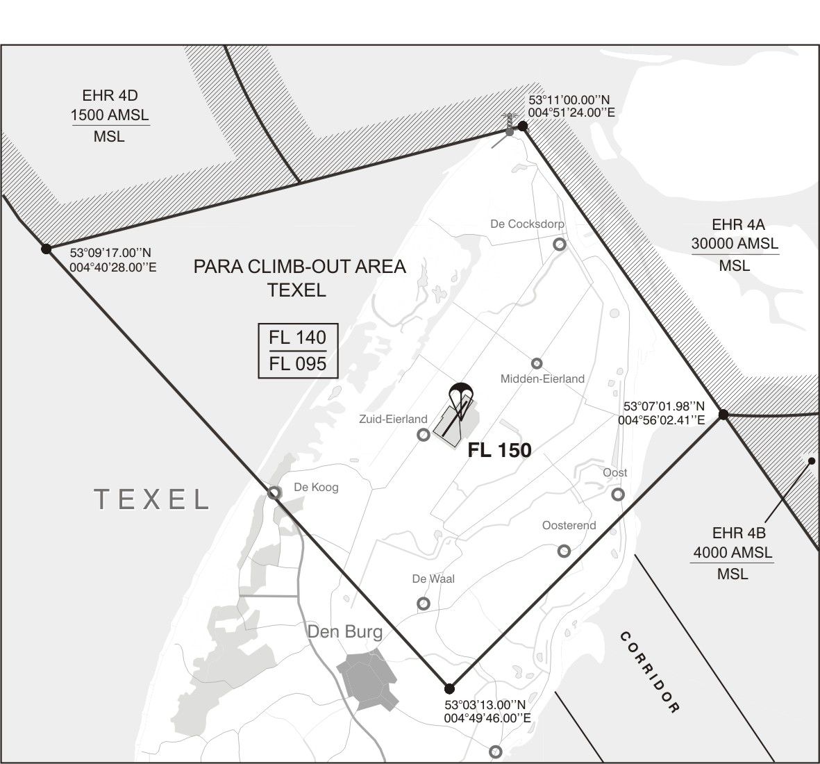
  1. Parachute jumping may take place in parachute jumping exercise area Texel and climb-out area Texel as specified in ENR 5.5.
  2. To accommodate parachute jumping from MAX FL 140 the para climb-out area Texel is established in EHTRA 10.
  3. Grass cutting may take place at irregular times.
EHTX AD 2.24 AERONAUTICAL CHARTS RELATED TO AN AERODROME
Charts
Pages
ADC
VAC - VFR procedures
Seasonal VFR arrival procedures RWY 03-21
Seasonal VFR departure procedures RWY 03-21
EHTX AD 2.25 VISUAL SEGMENT SURFACE (VSS) PENETRATION
NIL