EHTE AD 2.1 AERODROME LOCATION INDICATOR AND NAME
EHTE - DEVENTER/TEUGE
EHTE AD 2.2 AERODROME GEOGRAPHICAL AND ADMINISTRATIVE DATA
1
ARP coordinates and site at AD
521441N 0060248E
310 DEG GEO 575 M from AD office.
2
Direction and distance from (city)
3.0 NM W of Deventer; 1.5 NM NE of Apeldoorn.
3
Elevation / reference temperature
ELEV: 17 FT AMSL / T: 21 °C
4
Geoid undulation at AD ELEV PSN
142 FT
5
MAG VAR / annual change
2.8° E (2025) / 0.2° E
6
AD operator, address, telephone, telefax, email address, AFS, URL
TEUGE AIRPORT
DE ZANDEN 103 
7395 PG TEUGE
THE NETHERLANDS

TEL: +31 (0)55 323 8586
email: [email protected]
URL: https://www.teuge-airport.nl

7
Types of traffic permitted (IFR/VFR)
IFR/VFR
8
Remarks

- Aerodrome available for national and international civil air traffic with all types of aircraft, with wing span up to but not including 24 M and/or outer main gear wheel span up to but not including 6 M on the designated runways, and gliders on the indicated glider strips.
- Flights between EHTE and Schengen Treaty countries permitted.
- The import and export of cargo and cargo in transit is allowed.

Types of traffic permitted (IFR/VFR)
- IFR only allowed outside UDP BTN 0600-2200 (0500-2100).
EHTE AD 2.3 OPERATIONAL HOURS
1
AD operator
MON-FRI 0700-1900 (MON-FRI 0600-1800) during UDP
SAT 0800-1900 (SAT 0700-1800) during UDP
SUN HOL 0900-1900 (SUN HOL 0800-1800) during UDP

2
Customs and immigration
AVBL
3
Health and sanitation
NIL
4
AIS briefing office
H24
5
ATS reporting office (ARO)
H24
6
MET briefing office
NIL
7
ATS
NIL
8
Fuelling
MON-FRI 0700-1900 (MON-FRI 0600-1800) during UDP
SAT 0800-1900 (SAT 0700-1800) during UDP
SUN HOL 0900-1900 (SUN HOL 0800-1800) during UDP

9
Handling
AVBL
10
Security
NIL
11
De-icing
NIL
12
Remarks
AD operator
  • Jet aircraft and aircraft with MTOM above 6000 KG: 1 HR PPR.
  • IFR flights only allowed outside UDP BTN 0600-2200 (0500-2100), slots will be allocated by AD authority.
  • All flights outside OPR HR 24 HR PPR.
Customs and immigration
  • Customs: O/R; 24 HR PN.
  • Immigration: NIL.
Handling
  • Limited AVBL.
EHTE AD 2.4 HANDLING SERVICES AND FACILITIES
1
Cargo-handling facilities
NIL
2
Fuel / oil types
Fuel: JET A-1, AVGAS 100LL, Euro 98 (< 1% bio-ethanol)
Oil: NIL
3
Fuelling facilities/capacity
Self-service with Den Hartog card, debit card or credit card (VISA, Mastercard) only.
Jet-A1: 50 000 litres.
AVGAS 100LL: 25 000 litres.
Euro 98: 25 000 litres.

4
De-icing facilities
NIL
5
Hangar space for visiting aircraft
Limited AVBL.
6
Repair facilities for visiting aircraft
Major repairs to light aircraft up to 6000 KG.
7
Remarks
NIL
EHTE AD 2.5 PASSENGER FACILITIES
1
Hotels
At the aerodrome.
2
Restaurants
At the aerodrome.
3
Transportation
Bus to Apeldoorn and taxi (on request).
4
Medical facilities
In Deventer and Apeldoorn.
5
Bank and post office
Bank: In Twello, Deventer and Apeldoorn.
Post: In Twello, Deventer and Apeldoorn.
6
Tourist office
In Twello, Deventer and Apeldoorn.
7
Remarks
NIL
EHTE AD 2.6 RESCUE AND FIREFIGHTING SERVICES
1
AD category for firefighting
CAT 1
2
Rescue equipment
AVBL
3
Capability for removal of disabled aircraft
Hoist and lift capacity AVBL.
4
Remarks
AD category for fire fighting
  • CAT  2 or CAT 3 on request (12 HR PPR).
EHTE AD 2.7 RUNWAY SURFACE CONDITION ASSESSMENT AND REPORTING, AND SNOW PLAN
1
Types of clearing equipment
1 snowplough.
2
Clearance priorities
RWY, TWY, aprons.
3
Use of material for movement area surface treatment
NIL
4
Specially prepared winter runways
NIL
5
Remarks
Snow clearance of privately owned TWYs or aprons O/R. Clearing of airport infrastructure has priority.
EHTE AD 2.8 APRONS, TAXIWAYS AND CHECK LOCATIONS/POSITIONS DATA
1
Apron designation, surface and strength
Designation
Stand
Surface
Strength
Apron
  Asphalt and grass
12000 KG AUW
2
Taxiway designation, width, surface and strength
Designation of TWY
Width
Surface
Strength
TAXIWAY
10.0 M
Concrete and asphalt
BTN INT A-D PCR 58/F/B/Y/U; 
BTN INT D-E PCR 44/F/B/Y/U.

3
Altimeter checkpoint location and elevation
NIL
4
VOR checkpoints
NIL
5
INS checkpoints
NIL
6
Remarks
NIL
EHTE AD 2.9 SURFACE MOVEMENT GUIDANCE AND CONTROL SYSTEM AND MARKINGS
1
Use of aircraft stand ID signs, TWY guide lines and visual docking/parking guidance system at aircraft stands
TWY guide lines (yellow).
2
RWY and TWY markings and LGT
RWY markings
- 08: THR, designation, CL. 
- 26: THR, designation, CL, aiming point. 
- Glider landing area: yellow markers to separate aeroplane and glider area.

 
RWY LGT
- 08: THR, edge, RWY-end.
- 26: THR, edge, RWY-end.


TWY markings
- CL
- holding points including mandatory instruction signs at taxi holding point
- blue retro-reflective edge markers.
3
Stop bars
NIL
4
Remarks
NIL
EHTE AD 2.10 AERODROME OBSTACLES
For obstacles in the vicinity of the aerodrome see the aerodrome chart.
For obstacles in the take-off area see chart AOC type A RWY 08-26.
Area 2
OBST ID / designation
OBST type
OBST position
ELEV/HGT (FT)
Markings /
type, colour LGT

Remarks
1
2
3
4
5
6
NIL
Area 3
OBST ID / designation
OBST type
OBST position
ELEV/HGT (FT)
Markings /
type, colour LGT

Remarks
1
2
3
4
5
6
NIL
EHTE AD 2.11 METEOROLOGICAL INFORMATION PROVIDED
1
Associated MET office
NIL
2
Hours of service
MET office outside hours

Hours of service
NIL


MET office outside hours
NIL

3
Office responsible for TAF preparation
Period of validity


NIL
4
Trend forecast
Interval of issuance

NIL
5
Briefing/consultation provided
Available at the aerodrome office.
6
Flight documentation
Language(s) used

NIL
7
Charts and other information available for briefing or consultation
NIL
8
Supplementary equipment available for providing information
NIL
9
ATS units provided with information
NIL
10
Additional information (limitation of service, etc.)
NIL
EHTE AD 2.12 RUNWAY PHYSICAL CHARACTERISTICS
RWY designation
True BRG
Dimensions of RWY (M)
Strength (PCN) and surface of RWY and SWY
THR coordinates
RWY end coordinates
THR GUND

THR ELEV and highest ELEV of TDZ of precision APCH RWY
1
2
3
4
5
6
08
085.48°
1199 x 27
RWY: PCR: 58/F/B/Y/U
Concrete and asphalt
SWY: NIL
THR:
521432.82N 0060230.19E

RWY end: NIL
THR GUND: 142 FT
THR: 16 FT
TDZ: NIL
26
265.49°
1199 x 27
RWY: PCR: 58/F/B/Y/U
Concrete and asphalt
SWY: NIL
THR:
521435.62N 0060332.61E

RWY end: NIL
THR GUND: 142 FT
THR: 15 FT
TDZ: NIL
RWY designation
Slope of RWY-SWY
SWY dimensions (M)
CWY dimensions (M)
Strip dimensions (M)
RESA dimensions (M)
Location and description of arresting system
OFZ
1
7
8
9
10
11
12
13
08
NIL
NIL
60 x 140
1319 x 140
150 x 90
NIL
NIL
26
NIL
NIL
60 x 140
1319 x 140
130 x 86
NIL
NIL
RWY designation
Remarks
1
14
08
NIL
26
NIL
EHTE AD 2.13 DECLARED DISTANCES
RWY designator
TORA
(M)

TODA
(M)

ASDA
(M)

LDA
(M)

Remarks
1
2
3
4
5
6
08
1199
1259
1199
1199
NIL
26
1199
1259
1199
1199
NIL
EHTE AD 2.14 APPROACH AND RUNWAY LIGHTING
RWY
designator

APCH LGT
type
length
INTST

THR LGT
colour
WBAR

VASIS
location/slope
MEHT

TDZ LGT
length

RWY CL LGT
length
spacing
colour
INTST

1
2
3
4
5
6
08
NIL
G
NIL
NIL
NIL
NIL
26
NIL
G
NIL
PAPI
Left side/3.5°
40 FT
NIL
NIL
RWY
designator

RWY edge LGT
length
spacing
colour
INTST

RWY end LGT
colour
WBAR

SWY LGT
length
colour

Remarks
1
7
8
9
10
08
1199 M
60 M
W
LIH
R
NIL
NIL
NIL
26
1199 M
60 M
W
LIH
R
NIL
NIL
NIL
EHTE AD 2.15 OTHER LIGHTING, SECONDARY POWER SUPPLY
1
ABN/IBN location, characteristics and hours of operation
NIL
2
LDI location and LGT
Anemometer location and LGT

LDI: 100 M N of AD office.
Anemometer:  55 M NE of AD office.
3
TWY edge and centre line lighting
See EHTE AD 2.9.
4
Secondary power supply
Switchover time

AVBL
7 SEC.

5
Remarks
NIL
EHTE AD 2.16 HELICOPTER LANDING AREA
1
Coordinates TLOF or THR of FATO
Geoid undulation

NIL
2
TLOF and/or FATO elevation
NIL
3
TLOF and FATO area dimensions, surface, strength, marking
NIL
4
True BRG of FATO
NIL
5
Declared distances available
NIL
6
APCH and FATO lighting
NIL
7
Remarks
NIL
EHTE AD 2.17 AIR TRAFFIC SERVICES AIRSPACE
Designation and lateral limits
Vertical limits
Airspace classification
ATS unit
call sign
language(s)

Transition altitude
Hours of applicability
Remarks
1
2
3
4
5
6
7
NIL
NIL
G
NIL
NIL
NIL
NIL
EHTE AD 2.18 AIR TRAFFIC SERVICES COMMUNICATION FACILITIES
Service
designation

Call sign
Channel(s)
SATVOICE NR
Logon address
Hours of operation
Remarks
1
2
3
4
5
6
7
INFO
Teuge Radio
121.005
NIL
NIL
0600-2200 (0500-2100)
NIL
FIS
Dutch MIL Info
132.350
NIL
NIL
H24
PRI
Outside UDP.
ACS
Dutch MIL
128.355
NIL
NIL
H24
PRI
FIS only.
Outside UDP.

EHTE AD 2.19 RADIO NAVIGATION AND LANDING AIDS
Type of aid
MAG VAR
Supported OPS
ILS CAT
GBAS facility
(VOR/ILS/MLS declination)

ID
Frequency
CH
Service provider
Reference path ID

Hours of operation
Position of transmitting antenna
DME: ELEV
transmitting antenna
GBAS: ELEV
ellipsoid
height
reference point
SBAS: ellipsoid
height LTP/FTP

GBAS
reference
point
service
volume
radius

Remarks
1
2
3
4
5
6
7
8
GPS
NIL
L1
1575.42 MHz
H24
NIL
NIL
NIL
NIL
EGNOS
NIL
L1
1575.42 MHz
H24
NIL
NIL
NIL
See EHTE AD 2.22 for FAS data block
EHTE AD 2.20 LOCAL AERODROME REGULATIONS
NIL
EHTE AD 2.21 NOISE ABATEMENT PROCEDURES

1 USER REGULATIONS

  1. Executing circuit, sightseeing and training flights with helicopters is prohibited.
  2. Executing training flights with jet aircraft or propeller-driven aircraft with a maximum take-off mass of more than 6000 KG is prohibited.
  3. During the period of  April 15 until September 16 of each year the following regulations should be followed at Teuge Airport (times in UTC):
    1. Executing training and sightseeing flights is prohibited:
      1. On weekdays before 0600 and after 1800.
      2. On Saturdays before 0700 and after 1800.
      3. On Sundays and public holidays before 0800 and after 1800.
    2. Executing circuit flights for training purposes for take-off or landing or initiating go-around procedures with civil aircraft is prohibited:
      1. On weekdays before 0600 and after 1800.
      2. On Saturdays before 0700 and after 1600.
      3. On Sundays and public holidays before 0900 and after 1500.
    3. Taking-off with civil aircraft for executing banner towing flights is prohibited:
      1. On weekdays before 0600 and after 1800.
      2. On Saturdays before 0700 and after 1600, provided that, dropping the banner is permitted till 1800. Anyhow, during mentioned period it is possible to take-off from 0600 on for special events during a maximum of 3 Saturdays with prior permission.
    4. Executing flights for sport parachuting with civil aircraft is prohibited:
      1. On weekdays before 0600 and after 1800.
      2. On Saturdays before 0700 and after 1800.
      3. On Sundays and public holidays before 0800 and after 1800.
    5. Executing aerobatic flights with civil aircraft is prohibited:
      1. Above the aerodrome below an altitude of 1500 FT, except when taking part in an airshow, for which the minister has granted permission.
      2. On weekdays before 0600 and after 1800.
      3. On Saturdays before 0700 and after 1600.
      4. On Sundays and public holidays.
  4. Lift-off of hot air balloons from the aerodrome is only allowed after permission is granted by the (assistant) airport manager.
  5. Executing flights for parajumping with an aircraft with noiselevel of 69 dB(A) (Chapter 6) or 74.2 dB(A) (Chapter 10) or louder is prohibited on dates and times as published on the website www.teuge-airport.nl.

2 IFR PROCEDURES

Visual manoeuvring: circling south of AD prohibited.

3 VFR PROCEDURES

  1. Special attention is drawn to the visual circuit markers A, B, C, D, and E. These markers shall be used as turning points for a normal circuit.
  2. The south circuit must be left via the exits above the visual circuit markers A or E, depending on the runway in use.
  3. The south circuit must be approached via compulsory point SIERRA at an altitude of 717 FT AMSL as depicted on the visual approach chart.
  4. Marked and built-up areas must be avoided.
EHTE AD 2.22 FLIGHT PROCEDURES

1 INSTRUMENT DEPARTURE PROCEDURES

1.1 Introduction

Aerodrome operational information will be provided by the aeronautical station operator (Teuge Radio). Before commencing the IFR flight, the pilot will receive an en route clearance from MILATCC Schiphol relayed by Teuge Radio. All actions have been taken by the ATC units concerned to ensure separation from other flights after take-off.
 
Air traffic control service will be provided as soon as the aircraft has two-way radio contact with Dutch MIL.

1.2 Start-up and taxiing

Pilots of aircraft intending to carry out an IFR flight must contact the AD authority at least 15 MIN prior to the assigned time slot. After all preparations for departure have been made (doors closed etc.), pilots have to contact Teuge Radio before start-up. This call shall include:
  • aircraft identification (e.g. PHSPY).
  • position (e.g. opposite tower).
  • flight rules (e.g. IFR).
  • destination (e.g. Brussels).
  • request aerodrome information.

After co-ordination with the ATC unit(s) concerned, Teuge Radio will give a CTOT (calculated take-off time) and aerodrome information. Hereafter the pilot can start-up at own discretion.
 
The pilot shall be able to comply with the CTOT, since ATC planning of outbound traffic (involving en route clearance and co-ordination with adjacent ACCs) is based on the CTOT. Any delay shall be reported immediately to Teuge Radio. In case of indefinite delay, the probable duration of the delay must be given.
 
Taxiing and line-up is at pilot's own discretion. After lining up the pilot must switch the main communication set to Dutch MIL and the second communication set to Teuge Radio.

1.3 En route clearance

The en route clearance will be issued by the appropriate ATC unit (MILATCC Schiphol) to Teuge Radio and will be relayed by Teuge Radio to the departing aircraft as soon as possible after aerodrome information has been given. An en route clearance contains:
  1. Clearance limit: airport of destination.
  2. SSR code.
  3. ATC unit and COM channel on which the aircraft shall report as soon as possible after take-off.
  4. Departure instructions if applicable.

Example of an en route clearance: "PHSPY is cleared to Brussels, squawk 2123, after departure contact Dutch MIL 128.355."

1.4 Departure instructions

1.4.1 General remarks

  • Transition altitude: 3000 FT AMSL.
  • Turn radii based on a 25° bank angle.
  • MAX 250 KIAS below FL 100 unless otherwise instructed.
  • IFR departures only allowed outside UDP.

1.4.2 Departure procedure RWY 08

  • After take-off maintain track 083° MAG and proceed to DEVUT.
  • Contact Dutch MIL on 128.355 and climb to 2000 FT AMSL.
  • Overhead DEVUT at 2000 FT AMSL, proceed according to route clearance or under radar control by Dutch MIL.
Note:  pilots might experience difficulties in contacting the appropriate ATC unit at very low altitude due to the range of RTF equipment of MILATCC Schiphol (Dutch MIL).

1.4.3 Departure procedure RWY 26

  • After take-off maintain track 263° MAG, at 500 FT AMSL turn right inbound DEVUT.
  • Contact Dutch MIL on 128.355 and climb to 2000 FT AMSL.
  • Overhead DEVUT at 2000 FT AMSL, proceed according to route clearance or under radar control by Dutch MIL.
Note:  be aware of an obstacle ELEV 96 FT AMSL at position 550 M from the runway-end and 35 M left of the extended centre line.

1.5 Communication failure

The pilot of an IFR flight shall follow the general procedures for IFR flights (see ENR 1.3 paragraph "Communication Failure"). In addition the following applies during initial departure:
  1. When VMC:
    • Remain VMC and execute visual circuit.
  2. When IMC:
    • RWY 08: proceed directly to DEVUT.
    • RWY 26: continue on runway heading, at TE401 turn right inbound DEVUT.
    • Climb to 3000 FT AMSL.
    • Enter the holding for one complete pattern.
    • Execute an instrument approach procedure to RWY 26 (see chart IAC RNP RWY 26).

2 INSTRUMENT APPROACH PROCEDURES

2.1 Introduction

The instrument approach procedure is based on ICAO Annex 2 and ICAO Documents 4444-ATM/501 (PANS-ATM), 7030 (SUPPS) and 8168-OPS/611 (PANS-OPS).

The following restrictions apply for this instrument procedure:
  1. Instrument approach procedures are only allowed outside UDP BTN 0600-2200 (0500-2100).
  2. The number of flights that may use this procedure is restricted and prior permission is required. Requests are to be made at least 24 HR prior ETA, see EHTE AD 2.3.
  3. IFR training flights are not allowed.
  4. During the IFR approach procedure the pilot shall contact Dutch MIL on the main communication set and monitor Teuge Radio on the second communication set.

Below 1500 FT AMSL Dutch MIL will provide, as far as practicable, flight information service until the landing has been completed. Aerodrome information will be provided by Teuge Radio.
Before the flight will leave controlled airspace, all actions have been taken by the ATC units concerned to ensure separation from other known flights during the instrument approach procedure (incl. missed approach).

2.1.1 Authorisation required

Aircraft and crew have to comply with the relevant certification and operational requirements. That means that they are able to demonstrate compliance to the international (ICAO/EASA/EUROCAE) requirements. Especially EASA AMC 20-28 for LPV SBAS and AMC 20-27 for RNP APCH.

2.1.2 Radar procedures

During initial approach to Teuge, radar services may be provided by MILATCC Schiphol. Air traffic control service generally will be terminated when leaving controlled airspace.

2.2 Arrival

2.2.1 Inbound clearance

When entering the Amsterdam FIR a clearance will be issued, containing:
  1. Clearance limit.
  2. Route.
  3. Flight level.
  4. Runway in use.
  5. SSR code.

2.3 Initial and intermediate approach

2.3.1 Approach instructions

Approach instructions will be issued by MILATCC Schiphol, containing:
  1. Clearance limit, route and level.
  2. Runway in use.
  3. EAT, if holding procedures are applied.
  4. QNH Deelen.
  5. Transition level.
  6. MET information.
  7. Runway condition.

2.3.2 Transfer to Teuge Radio

Generally, before entering the intermediate approach segment, MILATCC Schiphol will issue clearance to carry out an instrument approach procedure (no landing clearance can be issued). Transfer of communication to Teuge Radio normally will take place after landing, when still on the runway.
Pilots should monitor Teuge Radio on a second communication set from the moment the FAF is overflown.

2.4 Final approach

2.4.1 Final approach procedures

2.4.1.1 General
For RWY 26 is an RNP approach available, as depicted on the instrument approach chart IAC RNP RWY 26. The full published instrument approach procedure is mandatory.
2.4.1.2 Visual manoeuvring (circling)
Circling north of AD to RWY 08 only.

2.4.2 Missed approach procedure

See approach chart IAC RNP RWY 26. In case the missed approach procedure has to be executed, MILATCC Schiphol has to be informed as soon as possible on the current COM channel.

2.4.3 Missed approach while circling to land RWY 08

If visual reference is lost the missed approach specified for RWY 26 shall be executed:
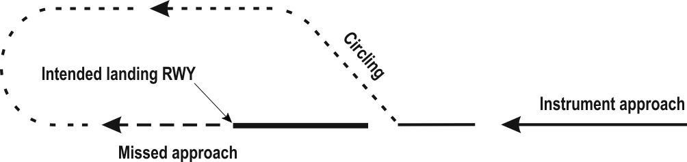
  • Inform ATC.
  • Climbing turn within the circling area to intercept 263° MAG inbound TE401 at circling altitude or higher;
  • Overhead TE401 turn right to proceed to DEVUT and continue climb to 3000 FT AMSL or altitude instructed by ATC.

2.5 Communication failure

2.5.1 General

The pilot of an IFR flight shall follow the general procedures for IFR flights (see ENR 1.3 paragraph "Communication Failure"). In addition the following applies.

2.5.2 Inbound clearance not received

  • Proceed according the current flight plan route to DEVUT.
  • Maintain the last cleared and acknowledged flight level.
  • After arrival over DEVUT, intercept the holding pattern.
  • Commence descent to 3000 FT AMSL at, or as near as possible to, the ETO over DEVUT.
  • After reaching 3000 FT AMSL leave DEVUT and execute an instrument approach procedure to RWY 26 (see chart IAC RNP RWY 26).

2.5.3 Inbound clearance received

  • Proceed according the current flight plan route to DEVUT.
  • Maintain the last cleared and acknowledged flight level.
  • After arrival over DEVUT, intercept the holding pattern.
  • Commence descent to 3000 FT AMSL at the EAT last received and acknowledged.
  • When no EAT has been received and acknowledged, commence descent to 3000 FT AMSL at, or as near as possible to, the ETO over DEVUT.
  • After reaching 3000 FT AMSL leave DEVUT and execute an instrument approach procedure to RWY 26 (see chart IAC RNP RWY 26).

2.5.4 Missed approach procedure

  • Track 263° MAG to TE401 and climb to 3000 FT AMSL.
  • At TE401 turn right inbound DEVUT and continue climb to 3000 FT AMSL.
  • Enter the holding for one complete pattern.
  • Execute the instrument approach procedure to RWY 26 again (see chart IAC RNP RWY 26).

2.5.5 Missed approach procedure in case of communication failure while circling to land RWY 08

  1. When visual:
    • Remain visual and execute another circuit for that runway.
  2. When unable to remain visual:
    • Climb to the circling altitude or higher.
    • Start the turn to TE401, at TE401 turn right to DEVUT and enter the holding at 3000 FT AMSL for one complete pattern.
    • Execute an instrument approach procedure to RWY 26 (see chart IAC RNP RWY 26).
Note:  circling south of AD prohibited.

2.5.6 Continue to alternate aerodrome after missed approach

  • Proceed to the alternate aerodrome contained in the flight plan following the most efficient routing, taking into account obstacle limitation and airspace restrictions.
  • Climb to a convenient level below FL 095 which is in accordance with the semi-circular table of cruising levels.
  • Proceed to the IAF for the main runway unless another runway is required for safety.
  • Enter the holding for one complete pattern.
  • Execute the instrument approach to the appropriate runway.
  • MILATCC Schiphol will take appropriate action to separate traffic accordingly and inform other ATC units.

2.6 Instrument approach description

2.6.1 RNAV procedure

Authorisation required, see EHTE AD 2.22 paragraph 2.1.1.

2.6.2 Instrument approach segments

Note:  for positions of EH waypoints see instrument approach chart IAC RNP RWY 26.
2.6.2.1 RNP RWY 26
Serial number Path
descriptor
WPT ident Fly over Course
MAG°/(T°)
MAG VAR Distance (NM) Turn Altitude (FT AMSL) Speed
(KIAS)
VPA (°) / TCH (FT) NAV
specification
001 IF DEVUT - - - - - + 3000 - 170 - RNP APCH
002 TF TE400 - 263 / (266.0) - 4.0 - + 3000 - - RNP APCH
003 TF RWY 26 Y 263 / (266.0) - 7.9 - - - -3.5 / 40 RNP APCH
004 TF TE401 Y 263 / (266.0) - 1.6 - - - - RNP APCH
005 DF DEVUT - - - - R @ 3000 - - RNP APCH
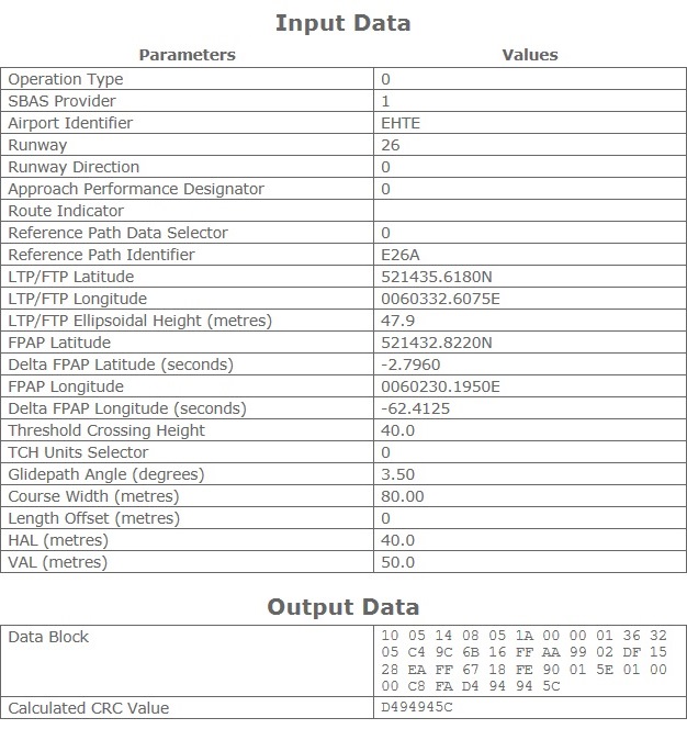
2.6.2.2 SBAS FAS data block coding data

 
Additional Data
Parameters Values
ICAO Code EH
LTP/FTP Orthometric Height (metres) 4.7

3 VFR FLIGHT PROCEDURES AND REGULATIONS

Note:  for VFR traffic circuit area see chart VAC - VFR procedures.

3.1 General

  1. The circuit area may not be overflown below an altitude of 1017 FT AMSL (1000 FT AAL).
  2. The standard circuit procedure is applicable for traffic in the circuit area (see ENR 1.2 paragraph 8). The circuit altitude is 717 FT AMSL (700 FT AAL). The visual traffic circuit must be carried out within the lateral limits of the circuit area appropriate to the runway in use.
  3. The visual departure procedures are specified in paragraph 3.2, leave the circuit by one of the exits indicated on chart VAC - VFR procedures.
  4. The visual approach procedures are specified in paragraph 3.3.
  5. A straight-in approach is possible for aircraft unable to follow the standard circuit for performance reasons. A straight-in is only allowed after coordination with Teuge Radio, report a straight-in well in advance. When established on final, also report "final straight in, two minutes out". When a go-around is required, leave the circuit area as published and report to Teuge Radio.
  6. Marked areas shall be avoided.
  7. Built-up areas shall be avoided as much as possible.
  8. Mind glider circuit and para jumping activities.
  9. The rules apply also to motor gliders.
  10. For taxi procedures see ground movement chart (GMC).
  11. Traffic in the traffic circuit has always right of way on approaching traffic.

3.2 Visual departure procedures

3.2.1 Departure RWY 08

  1. Climb to 717 FT AMSL (700 FT AAL) at the take-off leg.
  2. Leave the circuit via the exit above the visual circuit marker E, at an angle of 45° with the take-off leg, in northeasterly direction. This applies also for traffic with a southerly destination. This traffic will turn south between Twello and Deventer.
  3. If the altitude of 717 FT AMSL (700 FT AAL) is not yet reached over the visual circuit marker E, a climbing lefthand turn is allowed.

3.2.2 Departure RWY 26

  1. Climb to 717 FT AMSL (700 FT AAL) at the take-off leg.
  2. Leave the circuit via the exit above the visual circuit marker A, at an angle of 45° with the take-off leg, in northwesterly direction. This applies also for traffic with a southerly destination. This traffic will turn south, west of Apeldoorn.
  3. If the altitude of 717 FT AMSL (700 FT AAL) is not yet reached over the visual circuit marker A, a climbing righthand turn is allowed.

3.3 Visual approach procedures

3.3.1 Circuit area south RWY 08/26

  • Approach the south circuit via compulsory point SIERRA as depicted on chart VAC - VFR procedures. 
  • With many aircraft in or entering circuit area south, traffic separation may become critical. In that case, leave the pattern and make sure to maintain a safe distance to other traffic. When possible, climb to increase vertical separation from traffic at 717 FT AMSL. Rejoin the circuit via SIERRA and make sure other traffic near or arriving via SIERRA is not affected.  

3.3.2 Circuit area north RWY 08/26

The standard circuit procedure is applicable (see ENR 1.2 paragraph 9).

3.4 VFR traffic circuits

3.4.1 Circuit area south RWY 08/26

The visual circuit markers A, B, C, D and E, situated within the circuit area south RWY 08/26, must be used. These markers have to be used as turning points.

3.4.2 Circuit area north RWY 08/26

The standard circuit procedure is applicable (see ENR 1.2 paragraph 9).
EHTE AD 2.23 ADDITIONAL INFORMATION

1 CAUTIONS AND ADDITIONAL INFORMATION

  1. Glider flying may take place daily. The launching cable constitutes a dangerous obstacle up to 1700 FT AAL.
  2. The glider launching areas must be avoided.
  3. The aeroplane and glider areas are separated by yellow markers.
  4. Parachute jumping may take place in parachute jumping exercise area Teuge and climb-out area Teuge as specified in ENR 5.5. A "para's in one minute" call will be broadcasted one minute before every para dropping.
  5. Grass cutting may take place at irregular times.
EHTE AD 2.24 AERONAUTICAL CHARTS RELATED TO AN AERODROME
Charts
Pages
ADC
GMC
AOC type A RWY 08-26
IAC RNP RWY 26
VAC - VFR procedures
EHTE AD 2.25 VISUAL SEGMENT SURFACE (VSS) PENETRATION
NIL