|
1
|
ARP coordinates and site at AD
|
505457N 0054637E
081 DEG GEO 599 M from TWR. |
|
2
|
Direction and distance from (city)
|
5 NM NE of Maastricht.
|
|
3
|
Elevation / reference temperature
|
ELEV: 375 FT AMSL / T: 21.7 °C
|
|
4
|
Geoid undulation at AD ELEV PSN
|
150 FT
|
|
5
|
MAG VAR / annual change
|
3° E (2025) / 0.2° E
|
|
6
|
AD operator, address, telephone, telefax, email address, AFS, URL
|
MAASTRICHT AACHEN AIRPORT
P.O. BOX 1 6199 ZG MAASTRICHT AIRPORT THE NETHERLANDS TEL: +31 (0)43 358 9999 TEL: +31 (0)43 358 9750 (AIRPORT AUTHORITY) FAX: +31 (0)43 358 9977 (AIRPORT AUTHORITY) email: [email protected] URL: https://www.maa.nl |
|
7
|
Types of traffic permitted (IFR/VFR)
|
IFR/VFR
|
|
8
|
Remarks
|
2. Upon request, contact airport authority on channel 131.505. |
|
1
|
AD category for firefighting
|
CAT 7
|
|
2
|
Rescue equipment
|
1 light truck (4x4) with rescue equipment and 1 all-terrain vehicle (on scene commander).
|
|
3
|
Capability for removal of disabled aircraft
|
Mobile jack for ACFT up to MTOM 2000 KG. Other equipment via contractors.
|
|
4
|
Remarks
|
AD category for fire fighting
|
|
1
|
Use of aircraft stand ID signs, TWY guide lines and visual docking/parking guidance system at aircraft stands
|
|
|
2
|
RWY and TWY markings and LGT
|
RWY markings
|
|
3
|
Stop bars
|
|
|
4
|
Remarks
|
RWY markings
Start position marking see also EHBK AD 2.23. |
For obstacles in take-off area see AOC type A RWY 03-21.
No obstacle data sets available for area 2 and 3.
No obstacle data sets available for area 2 and 3.
|
1
|
Associated MET office
|
DE BILT
|
|
2
|
Hours of service
MET office outside hours |
Hours of service
H24 MET office outside hours NIL |
|
3
|
Office responsible for TAF preparation
Period of validity |
De Bilt
30 HR |
|
4
|
Trend forecast
Interval of issuance |
TREND
0455-2155 (0355-2055) |
|
5
|
Briefing/consultation provided
|
Self-briefing; briefing on request from MWO-De Bilt by telephone after self-briefing.
TEL: 0900 202 3341 Briefing low level flights (IFR/VFR). TEL: 0900 202 3343 Briefing IFR flights above FL 100. TEL: 0900 202 3340 Briefing balloon flights within Amsterdam FIR. Weather bulletin (Dutch language) and METARs via Dutch public television 'Teletekst' page 707. |
|
6
|
Flight documentation
Language(s) used |
Reports, forecasts, charts.
English, Dutch. |
|
7
|
Charts and other information available for briefing or consultation
|
S, P, W, T
|
|
8
|
Supplementary equipment available for providing information
|
WXR, APT
|
|
9
|
ATS units provided with information
|
Beek TWR, Beek APP
|
|
10
|
Additional information (limitation of service, etc.)
|
Briefing/consultation provided
- charge for TEL briefings and consultations is € 0,50/MIN. |
|
RWY designation
|
True BRG
|
Dimensions of RWY (M)
|
Strength (PCN) and surface of RWY and SWY
|
THR coordinates
RWY end coordinates THR GUND |
THR ELEV and highest ELEV of TDZ of precision APCH RWY
|
|---|---|---|---|---|---|
|
1
|
2
|
3
|
4
|
5
|
6
|
|
03
|
032.62°
|
2750 x 45
|
RWY: 88/F/B/X/T
PCR 832/F/B/X/T Asphalt SWY: NIL |
THR:
505406.65N 0054536.21E RWY end: 505514.79N 0054645.21E THR GUND: 150.0 FT |
THR: 365.5 FT
TDZ: 369.4 FT |
|
21
|
212.63°
|
2750 x 45
|
RWY: 88/F/B/X/T
PCR 832/F/B/X/T Asphalt SWY: NIL |
THR:
505507.97N 0054638.31E RWY end: 505359.84N 0054529.31E THR GUND: 150.0 FT |
THR: 370.7 FT
TDZ: 377.0 FT |
|
RWY designation
|
Remarks
|
|---|---|
|
1
|
14
|
|
03
|
- When temperature is 18°C or above, 180° turn not allowed on RWY 03/21 for ACFT with MTOM >= 50 000 KG.
- Jet ACFT doing a 180° turn on turn pad must keep power setting below breakaway thrust to avoid jet blast on the adjacent public road. - ACFT doing a 180° turn on turn pad shall turn anticlockwise. |
|
21
|
- When temperature is 18°C or above, 180° turn not allowed on RWY 03/21 for ACFT with MTOM >= 50 000 KG.
- Jet ACFT doing a 180° turn on turn pad must keep power setting below breakaway thrust to avoid jet blast on the adjacent public road. - ACFT doing a 180° turn on turn pad shall turn anticlockwise. - Some types of aircraft, including the B747-400, could have the propensity to land long on RWY 21 due to the shape of the runway slope. |
For determination of the datum line for intersection take-offs, see EHBK AD 2.23.
For local aerodrome restrictions on intersection take-offs, see EHBK AD 2.20.
For local aerodrome restrictions on intersection take-offs, see EHBK AD 2.20.
|
RWY designator
|
TORA
(M) |
TODA
(M) |
ASDA
(M) |
LDA
(M) |
Remarks
|
|---|---|---|---|---|---|
|
1
|
2
|
3
|
4
|
5
|
6
|
|
03
|
2500
|
2500
|
2500
|
2500
|
DTHR 250 M.
|
|
03
|
1152
|
1152
|
1152
|
NIL
|
Take-off from intersection with TWY: W4
|
|
21
|
2500
|
2500
|
2500
|
2500
|
DTHR 250 M.
|
|
21
|
1963
|
1963
|
1963
|
NIL
|
Take-off from intersection with TWY: E2
|
|
21
|
1624
|
1624
|
1624
|
NIL
|
Take-off from intersection with TWY: W3
|
|
21
|
1221
|
1221
|
1221
|
NIL
|
Take-off from intersection with TWY: W4
|
|
RWY
designator |
APCH LGT
type length INTST |
THR LGT
colour WBAR |
VASIS
location/slope MEHT |
TDZ LGT
length |
RWY CL LGT
length spacing colour INTST |
|---|---|---|---|---|---|
|
1
|
2
|
3
|
4
|
5
|
6
|
|
03
|
CAT I
608 M LIH |
G
NIL |
PAPI
Left side/3.0° 64 FT |
NIL
|
2500 M
15 M W LIH |
|
21
|
CAT II/III
855 M LIH |
G
NIL |
PAPI
Left side/3.0° 64 FT |
900 M
|
2500 M
15 M W LIH |
|
RWY
designator |
RWY edge LGT
length spacing colour INTST |
RWY end LGT
colour WBAR |
SWY LGT
length colour |
Remarks
|
|---|---|---|---|---|
|
1
|
7
|
8
|
9
|
10
|
|
03
|
2500 M
60 M W LIH |
R
NIL |
NIL
|
RWY CL LGT
Colour: white from THR to 900 M from RWY-end; white/red from 900 M from RWY-end to 300 M from RWY-end; red from 300 M from RWY-end to RWY-end. RWY edge LGT Colour: red BTN beginning of RWY pavement and DTHR; white BTN DTHR and 600 M from RWY-end; last 600 M to RWY-end yellow. RWY end LGT For landing, RWY end LGT are situated at the end of LDA. LED LGT LED lights used for APCH, PAPI, THR, CL, edge and end lights. |
|
21
|
2500 M
60 M W LIH |
R
NIL |
NIL
|
RWY CL LGT
Colour: white from THR to 900 M from RWY-end; white/red from 900 M from RWY-end to 300 M from RWY-end; red from 300 M from RWY-end to RWY-end. RWY edge LGT Colour: red BTN beginning of RWY pavement and DTHR; white BTN DTHR and 600 M from RWY-end; last 600 M to RWY-end yellow. RWY end LGT For landing, RWY end LGT are situated at the end of LDA. LED LGT LED lights used for APCH, PAPI, THR, TDZ, CL, edge and end lights. |
|
1
|
ABN/IBN location, characteristics and hours of operation
|
NIL
|
|
2
|
LDI location and LGT
Anemometer location and LGT |
LDI: NIL
Anemometer: 370 M FM THR, along RWY 03, at 105 M FM centre line near TDZ; 355 M FM THR, along RWY 21, at 112 M FM centre line near TDZ. |
|
3
|
TWY edge and centre line lighting
|
See EHBK AD 2.9.
|
|
4
|
Secondary power supply
Switchover time |
AVBL
0 seconds |
|
5
|
Remarks
|
NIL
|
|
Designation and lateral limits
|
Vertical limits
|
Airspace classification
|
ATS unit
call sign language(s) |
Transition altitude
|
Hours of applicability
|
Remarks
|
|
|---|---|---|---|---|---|---|---|
|
1
|
2
|
3
|
4
|
5
|
6
|
7
|
|
|
MAASTRICHT CTR
(EHBK)
|
Beek Tower
English |
3000 FT AMSL
|
0500-2300 (0400-2200)
|
NIL
|
|
Service
designation |
Call sign
|
Channel(s)
|
SATVOICE NR
|
Logon address
|
Hours of operation
|
Remarks
|
|---|---|---|---|---|---|---|
|
1
|
2
|
3
|
4
|
5
|
6
|
7
|
|
APP
|
Beek Approach
|
123.980
|
NIL
|
NIL
|
0500-2300 (0400-2200)
|
PRI
|
|
340.850
|
NIL
|
NIL
|
0500-2300 (0400-2200)
|
NIL
|
||
|
120.205
|
NIL
|
NIL
|
0500-2300 (0400-2200)
|
O/R or at ATC discretion.
|
||
|
TWR
|
Beek Tower
|
119.480
|
NIL
|
NIL
|
0500-2300 (0400-2200)
|
PRI
VDF, bearings class B. |
|
362.875
|
NIL
|
NIL
|
0500-2300 (0400-2200)
|
NIL
|
||
|
119.705
|
NIL
|
NIL
|
NIL
|
Guard
O/R or at ATC discretion. |
||
|
Beek Delivery
|
121.830
|
NIL
|
NIL
|
0500-2300 (0400-2200)
|
Start-up control and clearance delivery. Pre-flight information. IFR/VFR traffic (incl. training flights). VDF, bearings Class B.
|
|
|
ATIS
|
Maastricht Information
|
124.580
|
NIL
|
NIL
|
0500-2300 (0400-2200)
|
NIL
|
|
Type of aid
MAG VAR Supported OPS ILS CAT GBAS facility (VOR/ILS/MLS declination) |
ID
|
Frequency
CH Service provider Reference path ID |
Hours of operation
|
Position of transmitting antenna
|
DME: ELEV
transmitting antenna GBAS: ELEV ellipsoid height reference point SBAS: ellipsoid height LTP/FTP |
GBAS
reference point service volume radius |
Remarks
|
|---|---|---|---|---|---|---|---|
|
1
|
2
|
3
|
4
|
5
|
6
|
7
|
8
|
|
VOR/DME
(03° E) (decl.: 3°E) |
MAS
|
108.600 MHz
CH 23X |
505819.0N
0055737.5E |
300 FT
|
NIL
|
40 NM/250 FL
in sector 000°-360° MAG |
|
|
L
(02° E) |
NW
|
373 kHz
|
H24
|
510109.7N
0055242.0E |
NIL
|
NIL
|
NIL
|
|
DME 03
|
BKZ
|
CH 52Y
|
H24
|
505520.6N
0054647.2E |
400 FT
|
NIL
|
NIL
|
|
GP 03
|
BKZ
|
332.750 MHz
|
H24
|
505417.4N
0054539.8E |
NIL
|
NIL
|
NIL
|
|
LOC 03
(03° E) ILS CAT I/C/1 (decl.: 3°E) |
BKZ
|
111.550 MHz
|
H24
|
505519.4N
0054649.9E |
NIL
|
NIL
|
NIL
|
|
DME 21
|
BKN
|
CH 52Y
|
H24
|
505520.6N
0054647.1E |
400 FT
|
NIL
|
NIL
|
|
GP 21
|
BKN
|
332.750 MHz
|
H24
|
505502.1N
0054625.1E |
NIL
|
NIL
|
NIL
|
|
LOC 21
(03° E) ILS CAT III/E/4 (decl.: 3°E) |
BKN
|
111.550 MHz
|
H24
|
505356.7N
0054526.2E |
NIL
|
NIL
|
NIL
|
|
GPS
|
NIL
|
L1
1575.42 MHz |
H24
|
NIL
|
NIL
|
NIL
|
NIL
|
|
EGNOS
|
NIL
|
L1
1575.42 MHz |
H24
|
NIL
|
NIL
|
NIL
|
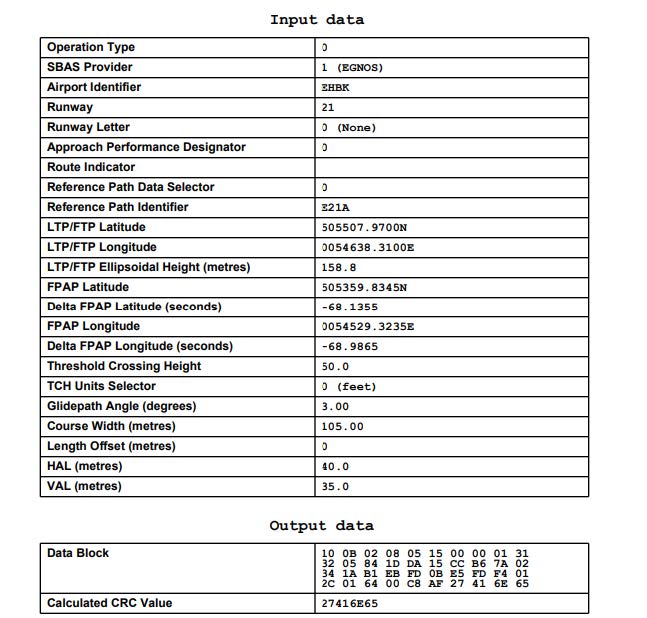
See EHBK AD 2.22 for FAS data block
|
| 1. | Flights with non noise certificated aircraft are not allowed. |
| 2. | So called "short approaches" to RWY 21 are not allowed within a distance of 4 NM. |
| 3. | ATC is not allowed to approve deviations from the SIDs except: |
| a. In emergency. | |
| b. When the aircraft has reached an altitude of 3500 FT AMSL for propeller aircraft and FL 060 for jet aircraft. | |
| 4. | Flights during night hours 2200-0500 (2100-0400) are not allowed without prior permission from the airport authority. |
| 5. | Visual approaches are not allowed during night hours 2200-0500 (2100-0400). ATC may allow or offer a visual approach: |
| a. In case of emergency. | |
| b. If no instrument approach is available. | |
| c. In exceptional cases to avoid a complicated air traffic flow. | |
| 6. | 180° turn not allowed on RWY 03/21 for ACFT MTOM >= 50 000 KG at OAT >= 18°C (according to METAR). |
| 7. | 180° turn not allowed on RWY 03/21 for ACFT CODE D/E/F. |
| 8. | Due to clearance requirements, aircraft types A346, A35F, A35K, B77W are restricted to park on stand B6 only. |
- Military training flights not allowed.
-
Circuit training only allowed MON-FRI 0800-1800 (MON-FRI 0700-1700), excluding HOL.
Additionally, circuit training for propeller powered aircraft with a MTOM <= 6000 KG, is allowed on MON-FRI 1800-2200 (MON-FRI 1700-2100), excluding HOL, after prior permission from airport authority. - Local IFR training flights shall file in item 15 the route description: DCT NOWIK.
Dropping or picking-up banners is not allowed.
Formation take-offs and landings are not allowed except with a pre-arranged operational agreement with ATC. Contact [email protected] for such an agreement.
- Before starting their engines pilots shall request start-up clearance from Beek Delivery.
- Pilots of aircraft intending to taxi on the taxiways shall obtain a clearance from Beek TWR.
- Aircraft not maintaining two-way radio communication and intending to taxi on the apron must obtain prior permission from the airport authority.
In general, an intersection take-off via TWY E2, W3 and W4 is only allowed for operational reasons. Furthermore the following restrictions apply for an intersection take-off via TWY W3 and W4:
RWY 03 (W4) or RWY 21 (W3 and W4):
RWY 03 (W4) or RWY 21 (W3 and W4):
Due to security reasons, handling is compulsory for all non based aircraft at Maastricht Aachen Airport. For handling companies see EHBK AD 2.23 paragraph 4.
The use of auxiliary power units (APU) is strictly controlled by Airport Authority at all aircraft stands. Flight crew are urgently requested to limit use of the APU as much as possible to reduce environmental and noise burden.
The APU should be shut down as soon as practicable following actual in block time (AIBT), but not later than 5 MIN after parking brakes set. Departing aircraft may start the APU not earlier than 15 MIN prior to actual off-block time (AOBT) in order to start engines. If the TOBT is delayed by more than 20 MIN the APU must be turned off again.
For cooling and heating purposes (zero emission) pre-conditioned air units (PCA)
Exceptions:
- When it is necessary to use the APU to ensure safety on board, at captain responsibility. Report to airport authority TEL: +31 (0)43 358 9750 as soon as practicable.
- When the outside temperature is below -5°C or above +25°C (according to METAR) the APU should not be restarted until actual start boarding time (ASBT).
- When it is necessary to use an APU to diagnose and/or rectify aircraft faults (for technical/maintenance reasons). Prior permission required from the Airport Authority, TEL: +31 (0)43 358 9750.
The use of aircraft engines for air-conditioning purposes on the apron is not allowed.
For contacting the Airport Authority: TEL +31 (0)43 358 9750. Do not use the Beek TWR channel or airport authority channel (131.505).
The APU should be shut down as soon as practicable following actual in block time (AIBT), but not later than 5 MIN after parking brakes set. Departing aircraft may start the APU not earlier than 15 MIN prior to actual off-block time (AOBT) in order to start engines. If the TOBT is delayed by more than 20 MIN the APU must be turned off again.
- When it is necessary to use the APU to ensure safety on board, at captain responsibility. Report to airport authority TEL: +31 (0)43 358 9750 as soon as practicable.
- When the outside temperature is below -5°C or above +25°C (according to METAR) the APU should not be restarted until actual start boarding time (ASBT).
- When it is necessary to use an APU to diagnose and/or rectify aircraft faults (for technical/maintenance reasons). Prior permission required from the Airport Authority, TEL: +31 (0)43 358 9750.
Aircraft identification should be entered before the transponder is activated (see also ENR 1.6 paragraph 2.1.1). Pilots must use the ICAO defined format as specified in ENR 1.10 paragraph 3.2.1 for entry of the aircraft identification.
All pilots shall select the assigned mode A (squawk) code and activate the mode S transponder:
Note:
activation of the mode S transponder means selecting AUTO mode, ON, XPNDR, or the equivalent according to specific installation. Selection of the STAND-BY mode will NOT activate the mode S transponder. Depending on the hardware configuration, selecting ON could overrule the required suppression of SSR replies and mode S all-call replies when the transponder is on the ground.
To ensure that the performance of systems based on SSR frequencies (including airborne TCAS units and SSR radars) is not compromised, TCAS should not be selected before receiving the clearance to line up. For arriving aircraft, TCAS should be deselected as soon as possible after vacating the runway.
All pilots shall select the assigned mode A (squawk) code and activate the mode S transponder:
To ensure that the performance of systems based on SSR frequencies (including airborne TCAS units and SSR radars) is not compromised, TCAS should not be selected before receiving the clearance to line up. For arriving aircraft, TCAS should be deselected as soon as possible after vacating the runway.
Due to limited parking availability all air carriers and aircraft operators planning to conduct non-scheduled flights for the purpose of carrying out maintenance (unscheduled/scheduled maintenance, repaint and/or parking/storage) on the aircraft require a PPR for that specific flight.
The coordination of PPR is performed at least 24 hours before scheduled time of arrival of the flight. Without approved PPR by Airport Authority no landing clearance will be provided by local ATC.
Requests for PPR shall be submitted to [email protected] including:- Operator
- Aircraft registration
- Type of Aircraft
- MTOW
- Noise certificate
- Flight number
- Date/time of inbound flight
- Date/time of outbound flight
- Responsible maintenance provider at Maastricht Aachen Airport
- Aircraft registration
- Type of Aircraft
- MTOW
- Noise certificate
- Flight number
- Date/time of inbound flight
- Date/time of outbound flight
- Responsible maintenance provider at Maastricht Aachen Airport
| Reference | Deviation | Related AIP section |
|---|---|---|
| 1 | 2 | 3 |
| Longitudinal slope changes on runway | ||
| CS ADR-DSN.B.065 (c)(1) | At RWY 03 and 21 the longitudinal slope locally exceeds 0.1% per 30 M. | EHBK AD 2.12 |
| Sight distance for slopes on runways | ||
| CS ADR-DSN.B.070 (b)(1) | From start of RWY 21 no unobstructed line of sight at 3 M. | EHBK AD 2.12 |
| Distance between slope changes on runways | ||
| CS ADR-DSN.B.075 | Deviation on curve is smaller than requirement due to geographical position of the aerodrome. | EHBK AD 2.12 |
| Transverse slopes on runway | ||
| CS ADR-DSN.B.080 (b)(1) | At RWY 03 and 21 the concrete part of the transverse slope is less than 1%. | EHBK AD 2.12 |
| CS ADR-DSN.B.080 (d) | At RWY 03 and 21 where concrete meets asphalt no even slope will be maintained. Will change from 1,5% for asphalt to ~1% for concrete. | EHBK AD 2.12 |
| Slopes on runway turnpads | ||
| CS ADR-DSN.B.100 | The slope on runway turnpad is sufficient for the drainage of water. However the slope of the turnpad is opposite to that of the runway pavement surface. | EHBK AD 2.12 |
| Objects on runway strips | ||
| CS ADR-DSN.B.165 (a) | Public roads and frangible airport fences are located in the runway strip. | EHBK AD 2.24 |
| Bird scaring cannons are located in the runway strip. | EHBK AD 2.24 | |
| Longitudinal slopes on runway strips | ||
| CS ADR-DSN.B.180 (b)(1) | The longitudinal slope on third-party territory along a portion of the strip exceeds 1.5%. | EHBK AD 2.24 |
| Objects on runway end safety areas | ||
| CS ADR-DSN.C.220 | Frangible airport fence, public road and service road are located in the runway end safety area of RWY 21. | EHBK AD 2.12 |
| General – Colour and conspicuity | ||
| CS ADR-DSN.L.520 (a) | To denote the 2500 M point to the pilot MAA has placed a dashed white line on the beginning of RWY 03. | EHBK AD 2.9 |
| Precision approach Category I lighting system | ||
| CS ADR-DSN.M.630 (b)(1) | Total length of lighting system is 608 M instead of 900 M. | EHBK AD 2.14 |
| Precision approach Category II and III lighting system | ||
| CS ADR-DSN.M.635 (a)(1) | Total length of lighting system is 855 M instead of 900 M. | EHBK AD 2.14 |
| CS ADR-DSN.M.685 (b)(1) | Runway end lights are not positioned at the end of the runway. | EHBK AD 2.14 |
| Electrical power supply systems | ||
| CS ADR-DSN.S.880 (d)(5) | Apron lights are not connected to the emergency power supply. | EHBK AD 2.15 |
| CS ADR-DSN.S.880 (d)(6) | Apron lights are not connected to the emergency power supply. | EHBK AD 2.15 |
| Electrical systems – Monitoring | ||
| CS ADR-DSN.S.890 (d) | No automatic relay to maintenance crew. Relay is via ATC. | NIL |
| CS ADR-DSN.S.890 (e) | No automatic relay to maintenance crew. Relay is via ATC | NIL |
Inbound aircraft shall adopt a continuous descent profile - to the greatest possible extent compatible with safe operation of the aircraft - by employing minimum engine thrust, ideally in a low drag configuration, prior to the FAF/FAP.
When cleared to descend via a standard arrival route, execute the lateral, vertical and speed profiles of the arrival procedure. In this case, the pilot is free to optimize descent and speed within the constraints as laid down in the procedure. The objective is to establish a low noise continuous descent approach.
When cleared to descend via a standard arrival route, execute the lateral, vertical and speed profiles of the arrival procedure. In this case, the pilot is free to optimize descent and speed within the constraints as laid down in the procedure. The objective is to establish a low noise continuous descent approach.
Full reverse thrust should not be used due to noise abatement. Full reverse thrust shall only be used when required for safety reasons.
The instrument departure procedures are based on ICAO Annex 2 and on ICAO Documents 4444-ATM/501 (PANS-ATM), 7030 (SUPPS) and 8168-OPS/611 (PANS-OPS). With respect to procedures extending outside the Maastricht TMA 1, special arrangements have been made between Beek APP/TWR and the appropriate German and Belgian ATC units.
Pilots of aircraft must have obtained start-up permission from ATC before starting their engines. A request for start-up shall be made to Beek Delivery after all preparations for departure have been made (doors closed etc.) and shall include:
Due to the short flying time to the FIR boundary, pilots of aircraft departing direction Belgium and Germany may request start-up permission before all preparations have been made, indicating the time at which they will be ready to start engines: "...... destination ..... ready to start engines at ......".
Permission for start-up will be issued as soon as possible after the request has been made to Beek Delivery. The pilot shall be able to comply with the start-up and taxi permission, since ATC planning of outbound traffic (involving en-route clearance and co-ordination with adjacent ATC units) is based on the start-up time. Any delay in start-up or taxiing shall be immediately reported to ATC. In case of indefinite delay the probable duration of the delay will be given.
During the hours of the ATIS broadcast no MET information will be issued to departing aircraft except RVR (see EHBK AD 2.18).
Permission for start-up will be issued as soon as possible after the request has been made to Beek Delivery. The pilot shall be able to comply with the start-up and taxi permission, since ATC planning of outbound traffic (involving en-route clearance and co-ordination with adjacent ATC units) is based on the start-up time. Any delay in start-up or taxiing shall be immediately reported to ATC. In case of indefinite delay the probable duration of the delay will be given.
During the hours of the ATIS broadcast no MET information will be issued to departing aircraft except RVR (see EHBK AD 2.18).
Instructions containing deviations from the standard instrument departure may be added to the en-route or take-off clearance. These instructions may comprise an opposite turn after take-off, maintaining a specified heading or temporary altitude restrictions; they amend the relevant part of the SID only.
Aircraft shall request taxi clearance on the TWR channel (see EHBK AD 2.18).
Pilots shall contact the adjacent ATC unit as soon as possible after they have been so instructed by ATC.
For the general procedures for IFR flights, see ENR 1.3 paragraph "Communication Failure".
Additionally, for departing flights, the following communication failure procedure applies:
- If a clearance to climb or re-routing instructions has not been given, comply with the route and altitude limitations detailed in the allocated standard instrument departure procedure or the departure instructions provided at take-off until the last waypoint has been reached.
Additionally, for departing flights, the following communication failure procedure applies:
- If a clearance to climb or re-routing instructions has not been given, comply with the route and altitude limitations detailed in the allocated standard instrument departure procedure or the departure instructions provided at take-off until the last waypoint has been reached.
- Transition altitude: 3000 FT AMSL.
- Pilots of departing aircraft shall remain on the TWR channel until passing 2000 FT AMSL . When passing 2000 FT AMSL pilots shall change to the APP channel and report the altitude in order for ATC to verify mode C.
- Initiate turns in due time in order not to overshoot radials.
- Turn radii based on a 25° bank angle.
- Radial interception angle: 45°.
- The SIDs are based on an average climb rate of 2000 FT/MIN.
- SIDs have to be considered as minimum noise routings which shall be strictly adhered to.
- MAX 250 KIAS below FL 100 unless otherwise instructed.
-
RNAV:
The Netherlands encourages the use of RNAV routes stored in a pre-programmed navigation database on board of aircraft. Although there may be differences between the RNAV and conventional description of a route (vertically: turn altitudes and/or laterally: turn anticipation effects), the resulting flight paths are considered identical by ATC. Therefore, flying the route using the RNAV coding from the navigation database will not result in route violations.
Furthermore:
- Pilots unable to comply with the crossing condition BK317 (2.5 MAS R-248) at or above 3500 FT AMSL, have to inform ATC before departure. The minimum climb gradient of 10.3 percent is required due to glider activities in ATZ Schinveld.
- Pilots unable to comply with the crossing condition at or above FL 045 or FL 060, have to inform ATC before departure. The minimum climb gradient is required due to the airspace structure.
- Only for aircraft with destination EHGG and EHLE, MAX FL 095.
- Only for aircraft with destination EHAM, MAX FL 075.
- Only for aircraft with destination EDDK.
- RNAV 1 required.
- SIDs RWY 21: early autopilot connection might result in turn initiation below 760 FT AMSL. If applicable, continue on track 210° MAG beyond 9.5 MAS to prevent turning below 760 FT AMSL.
See chart SID RWY 03.
|
LNO 4A
[LNO4A] |
See paragraph 1.4.2 specific remark: 2.
Minimum climb gradient: 5.8% to FL 060. Passing 2000 FT AMSL contact Beek APP 123.980. After departure climb to FL 060. |
||||||||||
| Serial number | Path descriptor | WPT ident | Fly-over |
Course/Track
°MAG / (°T) |
Recom. navaid | Dist. (NM) | Turn | Altitude (FT / FL) |
Speed
(KIAS) |
VPA (°) / TCH (FT) |
NAV
specification |
| 001 | CA | - | - | 030 / (032.8) | - | - | R | + 750 | - | - | RNAV 1 |
| 002 | DF | BK316 | N | - | - | - | - | + 2000 | - 220 | - | RNAV 1 |
| 003 | TF | BK318 | N | 155 / (157.3) | - | 10.7 | - | - | - | - | RNAV 1 |
| 004 | TF | ULPEN | N | 217 / (219.6) | - | 2.3 | - | + FL 060 | - | - | RNAV 1 |
| 005 | TF | LNO | N | 216 / (219.2) | - | 13.1 | - | - | - | - | RNAV 1 |
|
Conventional
description |
Lateral: Track 030° MAG. At 750 FT AMSL turn right to track 044° MAG. At 5.6 MAS turn right to track 155° MAG (MAX 220 KIAS) to intercept LNO R-036 inbound to LNO VOR. | ||||||||||
| Vertical: Cross 5.6 MAS at or above 2000 FT AMSL; 13.1 LNO at or above FL 060. | |||||||||||
|
NETEX 2A
[NETE2A] |
See paragraph 1.4.2 specific remark: 1, 2.
Minimum climb gradient: 10.3% to 3500 FT AMSL and 5.8% to FL 060. Passing 2000 FT AMSL contact Beek APP 123.980. After departure climb to FL 060. |
||||||||||
| Serial number | Path descriptor | WPT ident | Fly-over |
Course/Track
°MAG / (°T) |
Recom. navaid | Dist. (NM) | Turn | Altitude (FT / FL) |
Speed
(KIAS) |
VPA (°) / TCH (FT) |
NAV
specification |
| 001 | CA | - | - | 030 / (032.8) | - | - | R | + 750 | - | - | RNAV 1 |
| 002 | DF | BK315 | N | - | - | - | - | - | - | - | RNAV 1 |
| 003 | TF | BK317 | N | 067 / (070.3) | - | 3.6 | - | + 3500 | - | - | RNAV 1 |
| 004 | TF | MAS | N | 068 / (070.3) | - | 2.5 | - | - | - | - | RNAV 1 |
| 005 | TF | PIMIP | N | 026 / (028.7) | - | 4.7 | - | + FL 060 | - | - | RNAV 1 |
| 006 | TF | NETEX | N | 026 / (028.7) | - | 19.7 | - | - | - | - | RNAV 1 |
|
Conventional
description |
Lateral: Track 030° MAG. At 750 FT AMSL turn right to track 044° MAG to intercept MAS R-248 inbound to MAS VOR to intercept MAS R-026 to NETEX (24.4 MAS). | ||||||||||
| Vertical: Cross 2.5 MAS R-248 at or above 3500 FT AMSL; 4.7 MAS R-026 at or above FL 060. | |||||||||||
|
NVO 3A
[NVO3A] |
See paragraph 1.4.2 specific remark: 2, 5, 6.
Minimum climb gradient: 7.0% to 2000 FT AMSL and 5.5% to FL 060. Passing 2000 FT AMSL contact Beek APP 123.980. After departure climb to FL 060. |
||||||||||
| Serial number | Path descriptor | WPT ident | Fly-over |
Course/Track
°MAG / (°T) |
Recom. navaid | Dist. (NM) | Turn | Altitude (FT / FL) |
Speed
(KIAS) |
VPA (°) / TCH (FT) |
NAV
specification |
| 001 | CA | - | - | 030 / (032.8) | - | - | R | + 750 | - | - | RNAV 1 |
| 002 | DF | BK316 | N | - | - | - | - | + 2000 | - 220 | - | RNAV 1 |
| 003 | TF | BK319 | N | 155 / (157.3) | - | 8.8 | - | - | - | - | RNAV 1 |
| 004 | TF | ELBED | N | 084 / (086.5) | - | 4.3 | - | + FL 060 | - | - | RNAV 1 |
| 005 | TF | NVO | N | 086 / (089.1) | - | 22.0 | - | - | - | - | RNAV 1 |
|
OSGOS 2A
[OSGO2A] |
See paragraph 1.4.2 specific remark: 1, 6.
Minimum climb gradient: 10.3% to 3500 FT AMSL. Passing 2000 FT AMSL contact Beek APP 123.980. After departure climb to FL 060. |
||||||||||
| Serial number | Path descriptor | WPT ident | Fly-over |
Course/Track
°MAG / (°T) |
Recom. navaid | Dist. (NM) | Turn | Altitude (FT / FL) |
Speed
(KIAS) |
VPA (°) / TCH (FT) |
NAV
specification |
| 001 | CA | - | - | 030 / (032.8) | - | - | R | + 750 | - | - | RNAV 1 |
| 002 | DF | BK315 | N | - | - | - | - | - | - | - | RNAV 1 |
| 003 | TF | BK317 | N | 067 / (070.3) | - | 3.6 | - | + 3500 | - | - | RNAV 1 |
| 004 | TF | MAS | N | 068 / (070.3) | - | 2.5 | - | - | - | - | RNAV 1 |
| 005 | TF | OSGOS | N | 350 / (352.5) | - | 12.8 | - | + FL 060 | - | - | RNAV 1 |
|
PESER 4A
[PESE4A] |
See paragraph 1.4.2 specific remark: 1, 4, 6.
Minimum climb gradient: 10.3% to 3500 FT AMSL. Passing 2000 FT AMSL contact Beek APP 123.980. After departure climb to FL 060. |
||||||||||
| Serial number | Path descriptor | WPT ident | Fly-over |
Course/Track
°MAG / (°T) |
Recom. navaid | Dist. (NM) | Turn | Altitude (FT / FL) |
Speed
(KIAS) |
VPA (°) / TCH (FT) |
NAV
specification |
| 001 | CA | - | - | 030 / (032.8) | - | - | R | + 750 | - | - | RNAV 1 |
| 002 | DF | BK315 | N | - | - | - | - | - | - | - | RNAV 1 |
| 003 | TF | BK317 | N | 067 / (070.3) | - | 3.6 | - | + 3500 | - | - | RNAV 1 |
| 004 | TF | MAS | N | 068 / (070.3) | - | 2.5 | - | - | - | - | RNAV 1 |
| 005 | TF | OSGOS | N | 350 / (352.5) | - | 12.8 | - | + FL 060 | - | - | RNAV 1 |
| 006 | TF | SOPVI | N | 350 / (352.4) | - | 4.0 | - | - | - | - | RNAV 1 |
| 007 | TF | EHOJI | N | 302 / (304.7) | - | 23.1 | - | - | - | - | RNAV 1 |
| 008 | TF | BREDA | N | 283 / (285.5) | - | 21.0 | - | - | - | - | RNAV 1 |
| 009 | TF | PESER | N | 283 / (285.1) | - | 12.7 | - | - | - | - | RNAV 1 |
|
TENLI 2A
[TENL2A] |
See paragraph 1.4.2 specific remark: 1, 3, 6.
Minimum climb gradient: 10.3 % to 3500 FT AMSL. Passing 2000 FT AMSL contact Beek APP 123.980. After departure climb to FL 060. |
||||||||||
| Serial number | Path descriptor | WPT ident | Fly-over |
Course/Track
°MAG / (°T) |
Recom. navaid | Dist. (NM) | Turn | Altitude (FT / FL) |
Speed
(KIAS) |
VPA (°) / TCH (FT) |
NAV
specification |
| 001 | CA | - | - | 030 / (032.8) | - | - | R | + 750 | - | - | RNAV 1 |
| 002 | DF | BK315 | N | - | - | - | - | - | - | - | RNAV 1 |
| 003 | TF | BK317 | N | 067 / (070.3) | - | 3.6 | - | + 3500 | - | - | RNAV 1 |
| 004 | TF | MAS | N | 068 / (070.3) | - | 2.5 | - | - | - | - | RNAV 1 |
| 005 | TF | OSGOS | N | 350 / (352.5) | - | 12.8 | - | + FL 060 | - | - | RNAV 1 |
| 006 | TF | SOPVI | N | 350 / (352.4) | - | 4.0 | - | - | - | RNAV 1 | |
| 007 | TF | RUMER | N | 356 / (358.4) | - | 22.3 | - | - | - | RNAV 1 | |
| 008 | TF | BASGU | N | 353 / (355.8) | - | 17.6 | - | - | - | RNAV 1 | |
| 009 | TF | NIHOF | N | 065 / (068.3) | - | 15.9 | - | - | - | RNAV 1 | |
| 010 | TF | TENLI | N | 358 / (000.4) | - | 14.2 | - | - | - | - | RNAV 1 |
See chart SID RWY 21.
|
LNO 3B
[LNO3B] |
See paragraph 1.4.2 specific remark: 2, 7.
Minimum climb gradient: 6.6% to FL 060. Passing 2000 FT AMSL contact Beek APP 123.980. After departure climb to FL 060. |
||||||||||
| Serial number | Path descriptor | WPT ident | Fly-over |
Course/Track
°MAG / (°T) |
Recom. navaid | Dist. (NM) | Turn | Altitude (FT / FL) |
Speed
(KIAS) |
VPA (°) / TCH (FT) |
NAV
specification |
| 001 | CF | BK321 | N | 210 / (212.8) | MAS | - | - | - | - | - | RNAV 1 |
| 002 | TF | BK323 | N | 105 / (108.1) | - | 10.9 | - | - | - | - | RNAV 1 |
| 003 | TF | ULPEN | N | 217 / (219.5) | - | 3.8 | - | + FL 060 | - | - | RNAV 1 |
| 004 | TF | LNO | N | 216 / (219.2) | - | 13.1 | - | - | - | - | RNAV 1 |
|
Conventional
description |
Lateral: Track 210° MAG. At 9.5 MAS turn left to track 105° MAG. At LNO R-025 turn right to intercept LNO R-036 inbound to LNO VOR. | ||||||||||
| Vertical: Cross 13.1 LNO at or above FL 060. | |||||||||||
|
NETEX 2B
[NETE2B] |
See paragraph 1.4.2 specific remark: 2, 7.
Minimum climb gradient: 4.5% to FL 060. Passing 2000 FT AMSL contact Beek APP 123.980. After departure climb to FL 060. |
||||||||||
| Serial number | Path descriptor | WPT ident | Fly-over |
Course/Track
°MAG / (°T) |
Recom. navaid | Dist. (NM) | Turn | Altitude (FT / FL) |
Speed
(KIAS) |
VPA (°) / TCH (FT) |
NAV
specification |
| 001 | CF | BK320 | Y | 210 / (212.8) | MAS | - | - | - | - | - | RNAV 1 |
| 002 | CF | MAS | N | 036 / (038.7) | MAS | - | - | + FL 045 | - | - | RNAV 1 |
| 003 | TF | PIMIP | N | 026 / (028.7) | - | 4.7 | - | + FL 060 | - | - | RNAV 1 |
| 004 | TF | NETEX | N | 026 / (028.7) | - | 19.7 | - | - | - | - | RNAV 1 |
|
Conventional
description |
Lateral: Track 210° MAG. At 9.5 MAS turn left to intercept MAS R-216 inbound to intercept MAS R-026 to NETEX (24.4 MAS). | ||||||||||
| Vertical: Cross MAS at or above FL 045; 4.7 MAS R-026 at or above FL 060. | |||||||||||
|
NVO 3B
[NVO3B] |
See paragraph 1.4.2 specific remark: 2, 5, 6, 7.
Minimum climb gradient: 6.4% to FL 060. Passing 2000 FT AMSL contact Beek APP 123.980. After departure climb to FL 060. |
||||||||||
| Serial number | Path descriptor | WPT ident | Fly-over |
Course/Track
°MAG / (°T) |
Recom. navaid | Dist. (NM) | Turn | Altitude (FT / FL) |
Speed
(KIAS) |
VPA (°) / TCH (FT) |
NAV
specification |
| 001 | CF | BK321 | N | 210 / (212.8) | MAS | - | - | - | - | - | RNAV 1 |
| 002 | TF | BK319 | N | 105 / (108.1) | - | 9.1 | - | - | - | - | RNAV 1 |
| 003 | TF | ELBED | N | 084 / (086.5) | - | 4.3 | - | + FL 060 | - | - | RNAV 1 |
| 004 | TF | NVO | N | 086 / (089.1) | - | 22.0 | - | - | - | - | RNAV 1 |
|
OSGOS 2B
[OSGO2B] |
See paragraph 1.4.2 specific remark: 2, 6, 7.
Minimum climb gradient: 4.2% to FL 045. Passing 2000 FT AMSL contact Beek APP 123.980. After departure climb to FL 060. |
||||||||||
| Serial number | Path descriptor | WPT ident | Fly-over |
Course/Track
°MAG / (°T) |
Recom. navaid | Dist. (NM) | Turn | Altitude (FT / FL) |
Speed
(KIAS) |
VPA (°) / TCH (FT) |
NAV
specification |
| 001 | CF | BK320 | Y | 210 / (212.8) | MAS | - | - | - | - | - | RNAV 1 |
| 002 | CF | MAS | N | 036 / (038.7) | MAS | - | - | + FL 045 | - | - | RNAV 1 |
| 003 | TF | OSGOS | N | 350 / (352.5) | - | 12.8 | - | + FL 060 | - | - | RNAV 1 |
|
PESER 4B
[PESE4B] |
See paragraph 1.4.2 specific remark: 2, 4, 6, 7.
Minimum climb gradient: 4.2% to FL 045. Passing 2000 FT AMSL contact Beek APP 123.980. After departure climb to FL 060. |
||||||||||
| Serial number | Path descriptor | WPT ident | Fly-over |
Course/Track
°MAG / (°T) |
Recom. navaid | Dist. (NM) | Turn | Altitude (FT / FL) |
Speed
(KIAS) |
VPA (°) / TCH (FT) |
NAV
specification |
| 001 | CF | BK320 | Y | 210 / (212.8) | MAS | - | - | - | - | - | RNAV 1 |
| 002 | CF | MAS | N | 036 / (038.7) | MAS | - | - | + FL 045 | - | - | RNAV 1 |
| 003 | TF | OSGOS | N | 350 / (352.5) | - | 12.8 | - | + FL 060 | - | - | RNAV 1 |
| 004 | TF | SOPVI | N | 350 / (352.4) | - | 4.0 | - | - | - | - | RNAV 1 |
| 005 | TF | EHOJI | N | 302 / (304.7) | - | 23.1 | - | - | - | - | RNAV 1 |
| 006 | TF | BREDA | N | 283 / (285.5) | - | 21.0 | - | - | - | - | RNAV 1 |
| 007 | TF | PESER | N | 283 / (285.1) | - | 12.7 | - | - | - | - | RNAV 1 |
|
TENLI 2B
[TENL2B] |
See paragraph 1.4.2 specific remark: 2, 3, 6, 7.
Minimum climb gradient: 4.2% to FL 045. Passing 2000 FT AMSL contact Beek APP 123.980. After departure climb to FL 060. |
||||||||||
| Serial number | Path descriptor | WPT ident | Fly-over |
Course/Track
°MAG / (°T) |
Recom. navaid | Dist. (NM) | Turn | Altitude (FT / FL) |
Speed
(KIAS) |
VPA (°) / TCH (FT) |
NAV
specification |
| 001 | CF | BK320 | Y | 210 / (212.8) | MAS | - | - | - | - | - | RNAV 1 |
| 002 | CF | MAS | N | 036 / (038.7) | MAS | - | - | + FL 045 | - | - | RNAV 1 |
| 003 | TF | OSGOS | N | 350 / (352.5) | - | 12.8 | - | + FL 060 | - | - | RNAV 1 |
| 004 | TF | SOPVI | N | 350 / (352.4) | - | 4.0 | - | - | - | - | RNAV 1 |
| 005 | TF | RUMER | N | 356 / (358.4) | - | 22.3 | - | - | - | - | RNAV 1 |
| 006 | TF | BASGU | N | 353 / (355.8) | - | 17.6 | - | - | - | - | RNAV 1 |
| 007 | TF | NIHOF | N | 065 / (068.3) | - | 15.9 | - | - | - | - | RNAV 1 |
| 008 | TF | TENLI | N | 358 / (000.4) | - | 14.2 | - | - | - | - | RNAV 1 |
The arrival, instrument approach and holding procedures are based on ICAO Annex 2 and on ICAO Documents 4444-ATM/501 (PANS-ATM), 7030 (SUPPS) and 8168-OPS/611 (PANS-OPS). During initial and intermediate approach to Maastricht Aachen Airport radar services may be provided by Beek APP. With respect to procedures extending outside the Maastricht TMA 1, special arrangements have been made between Beek APP/TWR and the appropriate German and Belgian ATC units.
| LNO 1T | See paragraph 2.2.2.1 specific remark: 1. | |||
| ARINC designator | Formal description | Abbreviated description | Expected path terminator |
Fly-over
required |
| [LNO1T] | LNO | LNO | IF | N |
| To BERIR at or above 3000 FT AMSL | BERIR [A3000+] | TF | N | |
| MODRU 1T | See paragraph 2.2.2.1 specific remark: 1, 2. | |||
| ARINC designator | Formal description | Abbreviated description | Expected path terminator |
Fly-over
required |
| [MODR1T] | MODRU | MODRU | IF | N |
| To ANZUL at or above 3500 FT AMSL | ANZUL [A3500+] | TF | N | |
| NVO 1T | See paragraph 2.2.2.1 specific remark: 1. | |||
| ARINC designator | Formal description | Abbreviated description | Expected path terminator |
Fly-over
required |
| [NVO1T] | NVO | NVO | IF | N |
| To BAXIM at or above 4000 FT AMSL | BAXIM [A4000+] | TF | N | |
| To ANZUL at or above 3500 FT AMSL | ANZUL [A3500+] | TF | N | |
| NETEX 1T | See paragraph 2.2.2.1 specific remark: 1. | |||
| ARINC designator | Formal description | Abbreviated description | Expected path terminator |
Fly-over
required |
| [NETE1T] | NETEX | NETEX | IF | N |
| To BOBMO | BOBMO | TF | N | |
| To ANZUL at or above 3500 FT AMSL | ANZUL [A3500+] | TF | N | |
| OSGOS 1T | See paragraph 2.2.2.1 specific remark: 1, 3. | |||
| ARINC designator | Formal description | Abbreviated description | Expected path terminator |
Fly-over
required |
| [OSGO1T] | OSGOS | OSGOS | IF | N |
| To BOGRU | BOGRU | TF | N | |
| To ANZUL at or above 3500 FT AMSL | ANZUL [A3500+] | TF | N | |
| LNO 2M | See paragraph 2.2.2.1 specific remark: 1. | |||
| ARINC designator | Formal description | Abbreviated description | Expected path terminator |
Fly-over
required |
| [LNO2M] | LNO | LNO | IF | N |
| To BERIR | BERIR | TF | N | |
| To DINAK at or above 4000 FT AMSL | DINAK [A4000+] | TF | N | |
| MODRU 2M | See paragraph 2.2.2.1 specific remark: 1, 2. | |||
| ARINC designator | Formal description | Abbreviated description | Expected path terminator |
Fly-over
required |
| [MODR2M] | MODRU | MODRU | IF | N |
| To BOGRU at or above 3000 FT AMSL | BOGRU [A3000+] | TF | N | |
| NVO 3M | See paragraph 2.2.2.1 specific remark: 1. | |||
| ARINC designator | Formal description | Abbreviated description | Expected path terminator |
Fly-over
required |
| [NVO3M] | NVO | NVO | IF | N |
| To BAXIM | BAXIM | TF | N | |
| To DINAK at or above 4000 FT AMSL | DINAK [A4000+] | TF | N | |
| NETEX 2M | See paragraph 2.2.2.1 specific remark: 1. | |||
| ARINC designator | Formal description | Abbreviated description | Expected path terminator |
Fly-over
required |
| [NETE2M] | NETEX | NETEX | IF | N |
| To BOBMO | BOBMO | TF | N | |
| To BOGRU at or above 3000 FT AMSL | BOGRU [A3000+] | TF | N | |
| OSGOS 2M | See paragraph 2.2.2.1 specific remark: 1, 3. | |||
| ARINC designator | Formal description | Abbreviated description | Expected path terminator |
Fly-over
required |
| [OSGO2M] | OSGOS | OSGOS | IF | N |
| To BOGRU at or above 3000 FT AMSL | BOGRU [A3000+] | TF | N | |
Holding and entry procedures and the calculations of the associated protected areas are in accordance with PANS-OPS Volume II, part 4. Since separation is based on the calculated areas, compliance with these in-flight procedures is essential.
Navigation in the initial and intermediate approach segments is primarily based on vectors provided by ATC. Conventional initial and intermediate approach procedures to RWY 03 are available and will be used during COM failure or at ATC discretion.
There is no ILS approach with conventional initial and intermediate approach segment available to RWY 21. Non-RNAV 1 traffic should expect vectors provided by ATC to the final approach published on the chart IAC CDO approaches to ILS X CAT II & III or LOC X RWY 21.
Navigation in the initial and intermediate approach segments is primarily based on RNAV 1, followed by an ILS final approach. These can be initiated by ATC in order to reduce noise nuisance, fuel consumption, and to provide flexible and efficient ATC dispatch. The following ILS approaches with RNAV 1 segments are available:
These procedures are developed in accordance with ICAO PANS-OPS criteria with the following safeguards:
These approaches start at the IAF of the procedure and provide a lateral route onto the final approach. Altitudes and IAS will be as instructed by ATC. The approach clearance includes clearance to execute the ILS approach and intercept the glide path from the last instructed altitude. Further details are published on the relevant instrument approach charts.
Aircraft unable to meet the mentioned requirements shall react with the phraseology "UNABLE RNAV" if instructed to fly RNAV approach segments. These aircraft will be guided by vectors or rerouted via conventional navigation aids.
RNP approaches to LNAV, LNAV/VNAV and LPV minima are available for RWY 21.
For the use of an RNP approach it is required that the operator holds an RNP APCH operations approval issued by their State of registry. The approval should be compliant with EASA PART-ACNS or equivalent.
Aircraft unable to meet the mentioned requirements shall react with the phraseology "UNABLE RNP (APCH)" if instructed to fly RNP approach procedures. These aircraft will be guided by vectors, rerouted via ILS approaches or via conventional navigation aids
Note:
an aircraft vectored to intercept final approach shall report to ATC when established on the final approach track (ICAO Doc 4444-ATM/501 (PANS-ATM) chapter 8.9.4.1).
In principle the final approach will be conducted on the ILS of the main landing runway. Instrument approaches to RWY 03 and 21 can be made with the assistance of ILS, LOC, NDB (RWY 03 only) or RNP (RWY 21 only).
ATC will apply safeguards and procedures for ILS operations in relation to weather conditions to facilitate CAT I, CAT II and CAT III operations. However, it will be applied irrespective of the actual category of operations flown, which is on pilot's decision. As a consequence the approach clearance provided by ATC is based on traffic only. During the approach pilots will be informed of:
Pilots who wish to practise ILS CAT II or CAT III approaches have to request this on initial contact with Beek APP using the phrase: "Request practice CAT II or CAT III approach".
Due to possible roof top damage caused by aircraft on short final RWY 21, it is emphasized that no instrument and/or visual approach shall be made at an angle less than the ILS glide path or less than 5.2% (3.0 DEG) if no ILS is available.
To minimise noise nuisance, aircraft executing a visual approach shall intercept the final approach leg at an altitude of at least 1400 FT AMSL, unless residential areas can be avoided. Visual approaches during night hours are not allowed, see EHBK AD 2.20 paragraph 1.
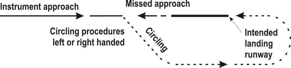
For each available landing runway at Maastricht Aachen Airport a circling approach may be allowed or offered. For OCA (OCH) see the relevant instrument approach chart.
All turns shall be the shortest turn and in case of a 180° turn that turn shall be to the left, unless otherwise specified below or instructed by ATC.
See the relevant instrument approach chart.
Note:
this procedure is different from ICAO Doc 8168 Volume I (PANS-OPS).
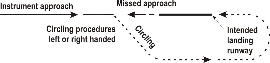
The pilot of an IFR flight shall follow the general procedures for IFR flights (see ENR 1.3 paragraph "Communication Failure"). Additionally, the below communication failure procedures apply for RNAV 1 traffic (paragraph 2.7.2) and non-RNAV 1 traffic (paragraph 2.7.3). See also paragraph 2.7.4 for missed approach procedures in case of communication failure.
Traffic cleared inbound an IAF or IF or cleared for an ILS or RNP APCH shall proceed to the IAF or IF and execute the approach procedure in accordance with the applicable instrument approach chart.
- Proceed direct to NOWIK and hold. Maintain the last cleared and acknowledged flight level.
- Commence descent to 3000 FT AMSL (transition altitude) as near as possible to the ETO over NOWIK.
- After reaching 3000 FT AMSL, leave NOWIK and proceed direct to the IAF or IF of an instrument approach procedure to the received and acknowledged runway, or to the landing runway according to ATIS (see the relevant instrument approach chart).
- Carry out the instrument approach procedure.
- Proceed direct to NOWIK. Maintain the last cleared and acknowledged flight level.
- Commence descent to 3000 FT AMSL (transition altitude) at the EAT last received and acknowledged.
- When no EAT has been received and acknowledged, commence descent to 3000 FT AMSL at or as near as possible to the ETO over NOWIK.
- After reaching 3000 FT AMSL, leave NOWIK and proceed direct to the IAF of an instrument approach procedure to the assigned runway, or to the landing runway according to ATIS (see the relevant instrument approach chart).
- Carry out the instrument approach procedure.
- Proceed direct to NOWIK and hold.
- Maintain the last cleared and acknowledged flight level.
- Commence descent to 3000 FT AMSL (transition altitude), if applicable.
- After reaching 3000 FT AMSL, leave NOWIK and proceed direct to the IAF of an instrument approach procedure to the assigned runway, or to the landing runway according to ATIS (see the relevant instrument approach chart).
- Carry out the instrument approach procedure.
- Maintain the last cleared and acknowledged level or climb to 3000 FT AMSL (minimum flight altitude), if applicable.
- Proceed to NOWIK.
- When over NOWIK, descend in the holding to 3000 FT AMSL (transition altitude), if applicable.
- After reaching 3000 FT AMSL, leave NOWIK and proceed direct to the IAF of an instrument approach procedure to the assigned runway or to the landing runway according to ATIS (see the relevant instrument approach chart).
- Carry out the instrument approach procedure.
- Maintain the last cleared and acknowledged level or MNM 3500 FT AMSL.
- Proceed to MAS VOR/DME.
- When over MAS VOR/DME descend, if applicable, to 3000 FT AMSL (transition altitude) while performing a left turn to intercept MAS R-214 and execute the instrument approach procedure again as depicted in chart IAC ILS Z or LOC Z RWY 03.
- Maintain the last cleared and acknowledged level or MNM 3000 FT AMSL.
- Proceed to MAS VOR/DME.
- When over MAS VOR/DME descend, if applicable, to 3000 FT AMSL (transition altitude) while intercepting MAS R-027 to DINAK (3.1 DME MAS).
- Turn left track 300º MAG to BOGRU (5.1 DME MAS).
- At BOGRU, turn left to execute the instrument approach procedure again.
All turns shall be the shortest turn and in case of a 180° turn that turn shall be to the left, unless otherwise specified below or instructed by ATC.
See the relevant instrument approach chart.
- Track 210° MAG and climb to 3000 FT AMSL.
- At 3.4 BKN beyond the runway turn left track 129° MAG.
- When passing 2300 FT AMSL turn left to cross MAS VOR/DME at 3000 FT AMSL.
- When over MAS VOR/DME intercept MAS R-027 to DINAK (3.1 DME MAS).
- Turn left track 300º MAG to BOGRU (5.1 DME MAS).
- At BOGRU turn left to execute the instrument approach procedure again.
Note:
this procedure is different from ICAO Doc 8168 Volume I (PANS-OPS).
|
Note:
recommended navaid for selection of MAG station declination only.
Note:
for positions of BK waypoints see relevant instrument approach charts.
| Serial number | Path descriptor | WPT ident | Fly-over |
Course/Track
°MAG / (°T) |
Recom. navaid | Dist. (NM) | Turn | Altitude (FT / FL) |
Speed
(KIAS) |
VPA (°) / TCH (FT) |
NAV
specification |
|---|---|---|---|---|---|---|---|---|---|---|---|
| 001 | IF | ANZUL | - | - | - | - | - | + 3500 | - | - | - |
| 002 | TF | BERIR | - | 211 / (213.9) | - | 5.1 | - | + 3000 | - | - | RNAV 1 |
| 003 | TF | BK302 | - | 302 / (304.8) | - | 5.0 | - | - | - 210 | - | RNAV 1 |
| 004 | CF | BK303 | - | 030 / (032.6) | BKZ | 1.6 | - | + 1800 | - | - | - |
| 005 | CF | THR 03 | Y | 030 / (032.6) | BKZ | 4.4 | - | - | - | -3.00 / 50 | - |
| 006 | FM | - | - | 030 / (032.6) | MAS | - | - | @ 2000 | - | - | - |
| Serial number | Path descriptor | WPT ident | Fly-over |
Course/Track
°MAG / (°T) |
Recom. navaid | Dist. (NM) | Turn | Altitude (FT / FL) |
Speed
(KIAS) |
VPA (°) / TCH (FT) |
NAV
specification |
|---|---|---|---|---|---|---|---|---|---|---|---|
| 001 | IF | DINAK | - | - | - | - | - | + 4000 | - 185 | - | - |
| 002 | CF | BOGRU | - | 300 / (302.8) | - | 3.9 | - | + 3000 | - 185 | - | RNAV 1 |
| 003 | CF | BK306 | - | 210 / (212.6) | BKN | 3.0 | - | + 2500 | - | - | - |
| 004 | CF | THR 21 | Y | 210 / (212.6) | BKN | 6.5 | - | - | - | -3.00 / 50 | - |
| 005 | FM | - | - | 210 / (212.6) | MAS | - | - | @ 2000 | - | - | - |
| Serial number | Path descriptor | WPT ident | Fly-over |
Course/Track
°MAG / (°T) |
Recom. navaid | Dist. (NM) | Turn | Altitude (FT / FL) |
Speed
(KIAS) |
VPA (°) / TCH (FT) |
NAV
specification |
|---|---|---|---|---|---|---|---|---|---|---|---|
| 001 | IF | DINAK | - | - | - | - | - | + 4000 | - 185 | - | - |
| 002 | TF | BOGRU | - | 300 / (302.8) | - | 3.9 | - | + 3000 | - 185 | - | RNP APCH |
| 003 | TF | BK201 | - | 210 / (212.7) | - | 3.9 | - | + 2200 | - | - | RNP APCH |
| 004 | TF | THR21 | Y | 210 / (212.7) | - | 5.6 | - | - | - | -3.00 / 50 | RNP APCH |
| 005 | TF | BK202 | - | 210 / (212.6) | - | 5.8 | - | @ 2000 | - | - | RNP APCH |

During periods of limited visibility the overall ATC capacity is reduced. To guarantee aircraft safety and optimal use of ATC capacity, Maastricht Aachen Airport uses ATC low visibility procedures. These procedures are based on ICAO DOC 9476/1 (Surface Movement Guidance and Control Manual) and ECAC DOC 17 (Ground operations in limited visibility conditions).
The ATC low visibility procedures are categorised in four phases (A, B, C, and D), that are based on visibility or RVR values and ceiling. The ATC low visibility procedures become effective when the general visibility equals or drops below 2000 M or when the lowest RVR equals or drops below 1500 M and/or ceiling is equal to or less than 300 FT.
First, the minimum separation for arriving aircraft and the departure interval will be increased. Next, runway use will be restricted.
Pilots should not request start-up permission unless the RVR values for the take-off runway are above the take-off limits for the flight. Pilots should be informed about the RVR minima that apply to their flight, so that they can readily respond to requests about these minima.
If the runway stop bars are out of service, additional restrictions apply.
During LVP all runway entries and runway crossings are safeguarded by switchable (remote controlled) or fixed stop bars (see chart ADC). Crossing of activated stop bars is prohibited. Traffic may proceed only after ATC clearance and when the stop bar lights are switched off (ICAO Annex 2).
Note:
for visual procedures and visual traffic circuits see the charts VAC - VFR procedures and VFR TFC circuits.
- All VFR flights within the Maastricht CTR and the Maastricht TMA 1 shall submit a flight plan (see ENR 1.10).
- Flying within the Maastricht CTR and the Maastricht TMA 1 is restricted to aircraft maintaining two-way radio communication with ATC, unless prior permission from ATC has been obtained. Such permission will only be given in extraordinary cases.
- Prior permission is required from Beek APP for all VFR operations in Maastricht TMA 1.
- Prior permission is required from Beek TWR for all VFR operations in the Maastricht CTR.
- VFR flights to and from Maastricht Aachen airport shall be carried out via the approach/departure routes unless otherwise instructed by ATC or when approved by ATC on pilot's request.
- Noise abatement has been included in the procedures.
- Built-up areas shall be avoided as much as possible.
- Marked areas shall be avoided.
- Schinveld ATZ is situated within the Maastricht CTR, for detailed information see ENR 5.1.
- Schinveld sector B (situated within the Maastricht CTR) will during set time period subject to local agreement be used by motorised local participants exempted from the mandatory transponder usage. VFR flights within the CTR may be instructed to stay outside the Schinveld sector B.
- IFR areas: VFR flights within the CTR may be instructed by ATC to stay clear of the specified IFR area. The IFR areas are indicated on the chart.
- VFR traffic instructed by ATC to squawk a specific SSR transponder code, shall maintain this squawk within the lateral limits of Maastricht TMA 1.
- VFR traffic following the Albert canal shall respect the Maastricht CTR boundary and contact Beek TWR for an entry clearance.
- Under the part of the Liège TMA Two in the Amsterdam FIR, FIS is provided by Brussels Information 126.900.
- VFR reporting points positions:
Note:
pilots operating outside the CTR should avoid crossing the final approach area of the instrument RWY 21 at altitudes at or near the initial approach altitude (3000 FT AMSL).
Note:
pilots are urgently requested not to execute VFR flights in the vicinity of the published instrument arrival and departure routes within the Maastricht TMA 1, which are published in EHBK AD 2.24.
- Pilots must have obtained start-up clearance from ATC before starting engines. A request for start-up shall be made to Beek Delivery; clearance for start-up will either be issued immediately or at a specified time depending on traffic. A request for start-up shall include:
- Taxiing on taxiways: pilots of aircraft intending to taxi on the taxiways shall obtain a clearance from Beek TWR.
- Taxiing on the apron: aircraft not maintaining two-way communication and intending to taxi on the apron must obtain prior permission from the airport authority.
- Departing aircraft shall climb as soon as possible and do not turn before passing the departure end of the runway.
-
Leave the CTR via an indicated route at 1300 FT AMSL.
RWY 03 BRAVO Departure After take-off turn left towards the canal and follow the VFR route to SIERRA and BRAVO. ZULU Departure After take-off turn left and follow the VFR route via GOLF, INDIA, VICTOR, PAPA to ZULU. Do not report over GOLF unless otherwise instructed by ATC. UNIFORM Departure After take-off turn right to follow the high tension line to HOTEL, then continue the route to UNIFORM. RWY 21 BRAVO Departure After take-off turn right and follow the VFR route via GOLF to BRAVO. Do not report over GOLF unless otherwise instructed by ATC. ZULU Departure After take-off turn right towards the canal and follow the VFR route via INDIA, VICTOR, PAPA to ZULU. UNIFORM Departure After take-off turn left and follow the VFR route via ROMEO to UNIFORM. Do not report over ROMEO unless otherwise instructed by ATC.
1. Contact Beek TWR 2 minutes before reaching the controlled airspace boundary, for permission to enter Maastricht TMA 1 and CTR.
Note : Maastricht TMA 1 airspace class D; two-way radio contact and entry clearance required.
2. Enter the CTR at 1800 FT AMSL and maintain this altitude, proceed via an indicated VFR route (BRAVO, UNIFORM or ZULU) unless otherwise instructed.
3. Pilots may be instructed to hold over the points SIERRA, HOTEL or INDIA.
4. Join the circuit as instructed by ATC.
5. In case of a missed approach climb straight ahead to 1300 FT AMSL and inform ATC.
Note : Maastricht TMA 1 airspace class D; two-way radio contact and entry clearance required.
2. Enter the CTR at 1800 FT AMSL and maintain this altitude, proceed via an indicated VFR route (BRAVO, UNIFORM or ZULU) unless otherwise instructed.
3. Pilots may be instructed to hold over the points SIERRA, HOTEL or INDIA.
4. Join the circuit as instructed by ATC.
5. In case of a missed approach climb straight ahead to 1300 FT AMSL and inform ATC.
Note:
western traffic circuit must be avoided as much as possible due to noise abatement; for traffic reasons pilots may be instructed to fly a western circuit.
Select SSR code 7600.
In case of communication failure adhere to the departure instructions if the departure instructions contain a clearance limit in the CTR, act in accordance with paragraph 4.5.4.
- In case of communication failure before joining the circuit, leave the CTR according to the BRAVO or ZULU Departure and divert to an appropriate aerodrome.
- In case of communication failure over or after a position from where to join the circuit (this is past the compulsory reporting point GOLF), execute a circuit for the last received and acknowledged runway as short as practicable. Make a full stop landing and vacate as soon as possible. In case of go-around execute a similar circuit (be aware of the fact that your flight path could interfere with the flight path of other aerodrome traffic).
- In case of communication failure before joining the circuit, leave the CTR according to the UNIFORM Departure and divert to an appropriate aerodrome.
- In case of communication failure over or after a position from where to join the circuit (this is past compulsory reporting point ROMEO), act in accordance with paragraph 4.5.3.1, item b.
In case of communication failure leave the CTR via the shortest route, maintain altitude until outside the CTR, do not cross runway centre lines or the IFR areas of RWYs 03 and 21 and proceed to an appropriate aerodrome.
- Pilots shall be aware that in the vicinity of the aerodrome ATC gives priority to:
- Bird-scare patrols are active 0500-2200 (0400-2100) and use various equipment, including remote control gas cannons, flare shell crackers, alternating bird dispersal guns and amplified cries of distress.
- When lightning discharges are observed in the vicinity of the airport, the airport authority officer (AAO) will announce that all ground handling and re-fuelling operations are prohibited until further notice. When it is safe to do so, the AAO will declare that ground handling and re-fuelling operations can be resumed.
- Aircraft making a 180° turn on the runway pavement shall ensure not to make a locked-wheel turn as this might result in runway pavement damage. In case the runway width is not sufficient, aircraft shall proceed to runway turn pad.
-
High visibility clothing is mandatory on
airside. all aprons. - Airport operations at both the passenger and cargo terminals will be completely halted if a power outage occurs. If an aircraft has already landed outside daylight hours prior to this outage, ground handling will only occur once mobile lighting has been installed to allow passengers to move safely and responsibly through the designated area. After this has been resolved, airport operations will be suspended until power is restored.
The datum line for take-off RWY 03 is located 150 M before threshold RWY 03. A dashed white line is placed 65 M in front of datum line to indicate starting position for take-off RWY 03. Aircraft shall not apply take-off thrust before passing the datum line.
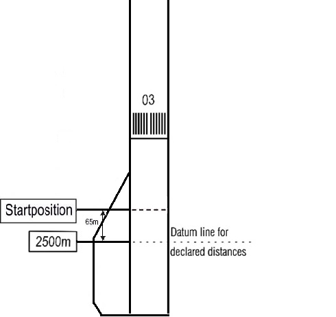
The datum line from which the reduced runway declared distances for take-off should be determined is defined by the intersection of the downwind edge of the specific TWY with the runway edge. The loss of runway length due to alignment of the aircraft prior to take-off shall be taken into account by the operators for the calculation of the aircraft's take-off mass (Annex 6, Part 1, paragraph 5.2.8).
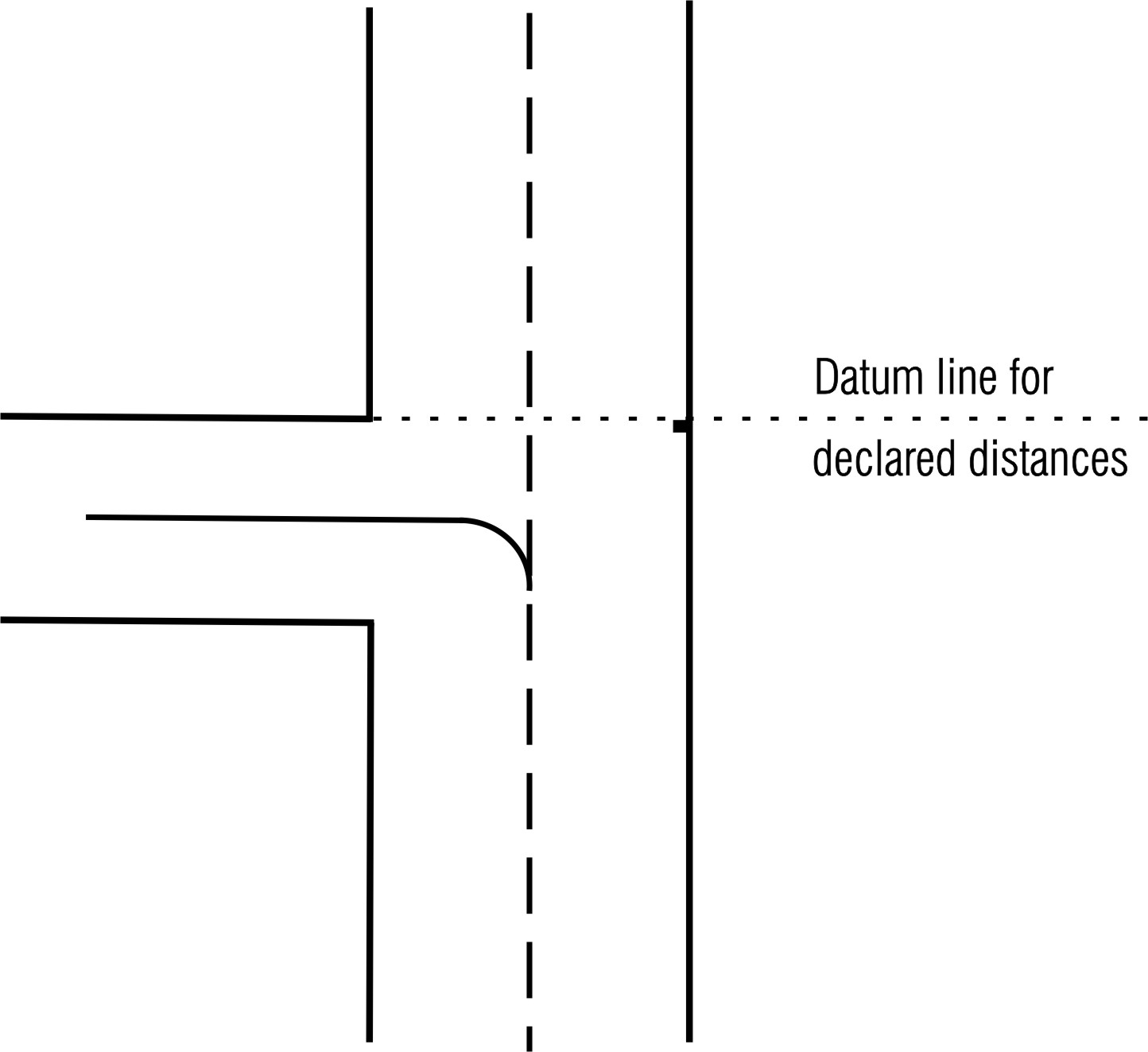
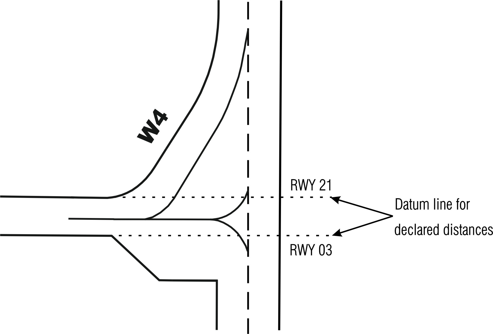
There is a runway turn pad situated at the runway extremity of RWY 21.
The turn pad is marked by a yellow guidance line, unidirectional green centre line lights and blue edge lights outside the edge of the turn pad. In the area of the turn pad, the edge of the runway is equipped with inset edge lights.
The turn pad is marked by a yellow guidance line, unidirectional green centre line lights and blue edge lights outside the edge of the turn pad. In the area of the turn pad, the edge of the runway is equipped with inset edge lights.
| 1. Commercial passengers and cargo | |
| Post: |
Handling Department Vliegveldweg 90 6199 AD Maastricht Airport |
| TEL: | +31 (0)43 358 9710 |
| Email: | [email protected] |
| SITA: | MSTAPXH |
| Note: | Maastricht Handling 131.755. |
| 2. Business and general aviation (equipped MAX 19 seats; handling compulsory for non-based aircraft) | |
| Post: |
Vliegveldweg 150 6199 AD Maastricht Airport |
| TEL: | +31 (0)43 762 0808 |
| Email: | [email protected] |
| Note: | handling requests shall be submitted prior to flight, via email or MyHandling (URL: cy.myhandlingsoftware.com). |
Operational restrictions on code letter F aircraft are shown on chart GMC B747-8F restrictions; see EHBK AD 2.24.
Operational restrictions are shown in the table below.
Operational restrictions are shown in the table below.
| Restrictions | |
| ILS landings | |
| All RWYs: ILS landings shall be made with coupled autopilot or flight director mode to ensure maximum track-accuracy to the runway centre line (see ICAO Circular 301). | |
| Taxiways and aprons | |
| TWY A and TWY W: prohibited for use by B747-8F. | |
| Apron A and C: prohibited for use by B747-8F. | |
| Intersections | |
| Intersection W3 and W4: prohibited for use by B747-8F. | |
| Aircraft stands (related to parking purposes only) | |
| B6, D3, D4: parking positions for arriving B747-8F. | |
| Engine run-up facilities | |
| Engine run-up area (towing only): no access due to wingspan restrictions. |
|
Charts
|
Pages
|
|---|---|
|
ADC
|

|
|
APDC
|
|
|
EHBK-GMC-B747
|
|
|
AOC type A RWY 03-21
|
|
|
PATC RWY 21
|
|
|
SID
|
|
|
SID RWY 03
|
|
|
SID RWY 21
|
|
|
STAR RWY 03
|
|
|
STAR RWY 21
|
|
|
ATCSMAC
|
|
|
IAC ILS Z or LOC Z RWY 03
|
|
|
IAC ILS Y or LOC Y RWY 03
|
|
|
IAC CDO approaches to ILS X or LOC X RWY 03
|
|
|
IAC NDB RWY 03
|
|
|
IAC CDO approaches to ILS X CAT II & III or LOC X RWY 21
|
|
|
IAC CDO approaches to RNP RWY 21
|
|
|
VAC - VFR procedures
|
|
|
VFR TFC circuits
|
|
To be developed.